


Chapter 3 Electrical Specifications
9
In
teg
ra
tio
n
Gu
id
e
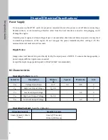
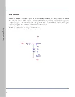
Power Supply
Do not power up the RT211 until it is properly connected. Be sure the power is cut off before connecting a
flexible cable to or disconnecting a flexible cable from the host interface connector. Hot-plugging could
damage the engine.
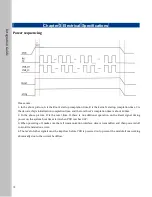
Unstable power supply or sharp voltage drops or unreasonably short interval between power-ons may lead
to unstable performance of the engine. Do not resupply the power immediately after cutting it off. The
minimum interval must exceed 2 seconds.
Ripple Noise
Image sensor and decoder chip are directly fed by the input power of RT211. To ensure the image quality, a
power supply with low ripple noise is needed.
Acceptable ripple range (peak-to-peak) : ≤50mV (≤30mV recommended).
DC Characteristics
Operating Voltage
Ta=23℃
Parameter
Description
Minimu
m
Typical
Maximum
Unit
V
DD
Voltage Drain Drain
3.15
3.3
3.45
V
V
IH
High Level Input Voltage
V
DD
-0.5
-
-
V
V
IL
Low Level Input Voltage
-
-
0.5
V
V
OH
High Level Output Voltage
V
DD
-0.3
-
-
V
V
OL
Low Level Output Voltage
-
-
0.3
V
Operating Current
Ta=23℃
,
VDD=3.3V
Operating Current
Standby Current
56mA (typical), 132mA
(max.)
3.4mA ( TTL mode)
55.2mA (USB mode)
Содержание RT211
Страница 1: ...Integration Guide RT211 OEM Scan Engine Integration Guide ...
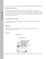
Страница 8: ...5 Integration Guide Vertical ...
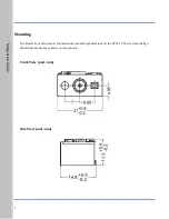
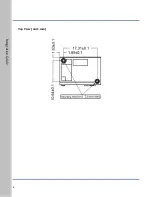
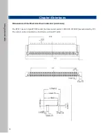
Страница 11: ...8 Integration Guide Top View unit mm ...


