background image

R60-IO

User Manual

-6-

szruitech.com

3.4 Control signal connection

3.4.1

IN Port: connection for pulse command

The upper controller can be the pulse signal generating device, such as PLC, MCU, control card and
controller.

The pulse level that R60-IO drive can be used: 3.3V-24V (

no need to connect resistor

)

S

p

e

e

d
m

o

d

e
1

In1

In2

不 转

正 转

反 转

不 转

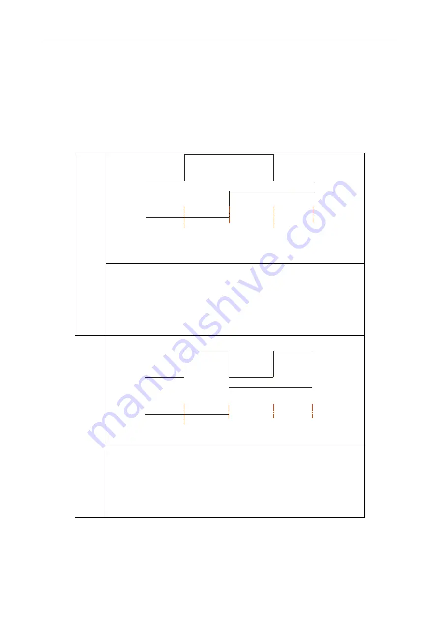
When IN1 is turned on and IN2 is turned off, the motor is triggered to rotate
forward; when IN1 is turned off, the motor decelerates to stop.
When IN1 is turned on and IN2 is turned on, the motor is reversed. When IN1 is
turned off, the motor decelerates to a stop.
When IN1 is off, the motor stops running.

(default is this mode)

S

p

e

e

d
m

o

d
2

In1

In2

不 转

正 转

反 转

不 转

When IN1 is turned on, the motor is triggered to continue to rotate forward;
when it turns from on to off, the motor decelerates and stops.
When IN2 is turned on, the motor is triggered to continuously reverse; when it
turns from on to off, the motor decelerates and stops.
When IN1 and IN2 are both on, the motor will stop running.

Note: The IO driver defaults to mode 1. If you need to adjust, please explain to Rtelligent.

3.4.2

ENA port: used to enable or disable.

By default, the driver outputs current to the motor when the photocoupler is turned off. When the

Do not turn

Forward

Reverse

Do not turn

Reverse

Do not turn

Forward

Do not turn

Содержание R60-IO

Страница 1: ...R60 IO User Manual Shenzhen Rtelligent Mechanical Electrical Technology Co Ltd...

Страница 2: ...3 2 Power supply input 4 3 3 Motor connection 5 3 4 Control signal connection 6 3 4 1 IN Port connection for pulse command 6 3 4 2 ENA port for potentiometer speed control 6 4 The setting of DIP switc...

Страница 3: ...O trigger fixed speed motion Power supply 24 48VDC Output Current Up to 5 6 amps peak value Current control PID current control algorithm Micro stepping settings DIP switch settings 16 options Speed r...

Страница 4: ...vertically or horizontally with its front facing forward top facing upward to facilitate cooling During assembly avoid drillings and other foreign matters falling inside the drive During assembly plea...

Страница 5: ...t current control The drive output the voltage to motor by changing the input power into PWM chopping wave when it is working In this case the input power will affect the performance of drive Power se...

Страница 6: ...inductance hybrid stepper motor The common 2 phase stepper motor s lead number are 4 8 and 6 There is only one connection mode for 4 leads motor Series and parallel connection mode are used by 8 leads...

Страница 7: ...f the motor decelerates to a stop When IN1 is off the motor stops running default is this mode S p e e d m o d 2 In1 In2 When IN1 is turned on the motor is triggered to continue to rotate forward when...

Страница 8: ...ent can be custom made 2 1A 1 5A off on on 2 7A 1 9A on off on 3 2A 2 3A off off on 3 8A 2 7A on on off 4 3A 3 1A off on off 4 9A 3 5A on off off 5 6A 4 0A off off off DIP SW1 SW2 SW3 are used to set...

Страница 9: ...tion of the motor when it is running Off means the acceleration gear position 1 and the acceleration is moderate On means the acceleration gear position 2 and the acceleration is large The default acc...

Страница 10: ...SW5 The motor cable is disconnected Check the connection The motor has only one direction Pulse mode error or DIR port damaged Alarm indicator is on The motor connection is wrong Check the motor conne...

Страница 11: ...ause A 1 Warranty period 12 months We provide quality assurance for one year from the date of delivery and free maintenance service for our products during the warranty period A 2 Exclude the followin...

Отзывы: