UPS25 23
RTD Embedded Technologies, Inc
Ni-Mh\Ni-Cd battery charger
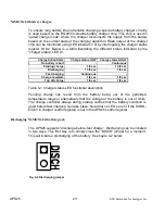
To ensure long battery life and reliable charging a special battery charger circuitry
is used based on the BQ2003 versatile battery charger chip. This chip is used in
“gated charge mode” where the charger disconnects the supply from the battery
based on the current state of the charging algorithm. State output of the charger
chip can be monitored using LED labeled L3 or by interrogating the charger status
register bit #2. Below is a table illustrating the different states indicated by the
“charger status” LED L3.
Charge Action State
Charge status LOW
Charge status HIGH
No battery / abort
-
Continuous
Pending charge
1/8 sec
1 3/8 sec
Discharging
1 3/8 sec
1/8 sec
Fast charging
Continuous
-
Charge complete
1/8 sec
1/8 sec
Top off charge
1/8 sec
1/8 sec
Table 4-1 Charger status LED functional description
Pending charge can result from the battery being out of the permitted
temperature range or alternatively that the voltage of the battery is out of limits.
The charge controller always during startup verifies that the battery condition is
good before fast charging can take place. Note that no LED’s are lit if the SHDN-
bit (#3 in charger control register) is set in the UPS25 control register.
Discharging Ni-Mh/Ni-Cd battery pack
The UPS25 supports “discharge-before-fast charge”. Discharging can be initiated
in two ways. The first way is to simply close the “DISCH” jumper for a moment.
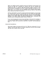
This will initiate a discharging of the battery. See figure 4-2 below:
Fig. 4-2 Discharging jumper
Содержание UPS25
Страница 39: ...UPS25 39 RTD Embedded Technologies Inc...


