background image


Page 12 of 12 


SPI 

www.rotork.com 


PUB132-002-00_0219 

11


Spare Parts 

As SPI units are sealed and qualified for life, replacement of parts does not extend this qualified life. If it is 
desired that an inspection of the SPI unit be carried out, Rotork can perform the inspection and will, where 
required, replace all screws, O-rings, bearings and grease when re-building the SPI unit. Please note that all 
records relating to spare parts are to be maintained by the unit owner. 

12


Torque Tightening Figures 

The values for the torque tightening the required fasteners are given in the following table. For all other 
fasteners not covered below please contact Rotork. 

FASTENER SIZE 

TORQUE TIGHTNESS (Nm) 

TORQUE TIGHTNESS (lb ft.) 

M2.5 

0.5 

0.4 

M3 

1.0 

0.7 

M4 

2.2 

1.6 

M5 

4.5 

3.3 

M6 

7.7 

5.7 


13


SPI Approvals 

Refer to product nameplate for unit specific approval details. 

European 

 Hazardous Area 

International 

 Hazardous Area 

International 


Non Hazardous 

ATEX (2014/34/EU) 

IEC 60079-0:2011 Ed 6 
IEC 60079-1:2007 Ed 6 
IEC 60079-7:2006 Ed 4 
IEC 60079-11:2011 Ed 6 
IEC 60079-31:2013 Ed 2 
ISO 80079-36:2016 Ed 1 
ISO 80079-37:2016 Ed 1 

Watertight & 

Dust-tight 

BS EN 60529 IP67 

T ambient = 

-25°C to +100°C 

On versions fitted with flameproof 
micro-switches: 

On versions fitted with flameproof 
micro-switches: 

 II 2GD 

Ex e d IIC T4 Gb 
Ex h IIC T4 Gb 
Ex tb IIIC T135°C Db IP67 
T ambient = -25°C to +65°C (1.5 A 
version) or -25°C to +40°C (5 A version) 

Ex e d IIC T4 Gb 
Ex h IIC T4 Gb 
Ex tb IIIC T135°C Db IP67 
T ambient = -25°C to +65°C (1.5 A 
version) or -25°C to +40°C (5 A version) 

On versions fitted with intrinsically safe 
proximity sensors: 

On versions fitted with intrinsically safe 
proximity sensors: 

 II 2G 

Ex ib IIC T4 Gb 
Ex h IIC T4 Gb 
T ambient = -25°C to +100°C  

Ex ib IIC T4 Gb 
Ex h IIC T4 Gb 
T ambient = -25°C to +100°C  

Document Change History 

See Bluestar for revision history 

Table 1 

 Torque Tightening Figures 

Содержание SPI 1

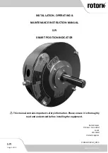
Страница 1: ...OPERATING MAINTENANCE INSTRUCTION MANUAL SPI SMART POSITION INDICATOR This manual contains important safety information Please ensure it is thoroughly read and understood before installing the equipme...

Страница 2: ...Spare Parts 12 12 Torque Tightening Figures 12 13 SPI Approvals 12 List of Figures Figure 1 SPI Thrust Taking Output Sleeve Assembly 7 Figure 2 SPI Thrust Bearing Arrangement 7 Figure 3 SPI Output Sl...

Страница 3: ...as outlined in this manual and also in accordance with relevant standards such as British Standard Codes of Practice and EN IEC 60079 14 If the product has nameplates indicating that it is suitable f...

Страница 4: ...gh speed device such as a drill etc 2 Specific Conditions of Use for Hazardous Area Approved Units 1 This equipment incorporates an anodized outer surface To avoid the possibility of electrostatic cha...

Страница 5: ...For Ex i Ex h product variants Ui 16V Ii 25 mA Pi 64 mW per separate IS circuit 3 4 Operational Specifications Life 2 million input shaft turns each direction Duty Manual operation service as per par...

Страница 6: ...andling The actuating gearboxes and SPI units must be fully supported until full valve shaft stem engagement is achieved and the actuating gearbox or SPI is secured to the valve flange Once connected...

Страница 7: ...correct position to ensure drive from the SPI output shaft Applying a thin layer of grease to the faces marked A below will make refitting of the output sleeve easier WARNING Ensure the correct order...

Страница 8: ...bearings may become damaged and will require replacing The SPI is supplied with studs and nuts for mounting to the valve or gearbox If it is desired to replace these we recommend grade 8 8 fasteners 6...

Страница 9: ...ening torque must not exceed 1 5 Nm 1 1 lb ft 13 2 lb in WARNING When connecting conductors make sure that the wire insulation extends right up to the terminal point WARNING Earth continuity is assure...

Страница 10: ...r valve positions between 60 open and fully open a If this feature is desired turn the input shaft of the SPI to the chosen valve position between 60 open and fully open and follow steps 17 and 18 to...

Страница 11: ...erious injury 9 Maintenance All mechanical cavities are lubricated with Fuchs Renolit CLX2 grease and sealed for life Annual functional check of the SPI is recommended Under normal operating condition...

Страница 12: ...ific approval details European Hazardous Area International Hazardous Area International Non Hazardous ATEX 2014 34 EU IEC 60079 0 2011 Ed 6 IEC 60079 1 2007 Ed 6 IEC 60079 7 2006 Ed 4 IEC 60079 11 20...

Отзывы: