


BRP-Rotax
INSTALLATION MANUAL
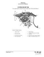
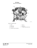
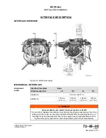
INTERFACE DESCRIPTION
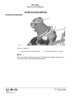
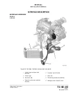
INTERFACE OVERVIEW
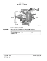
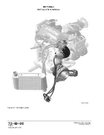
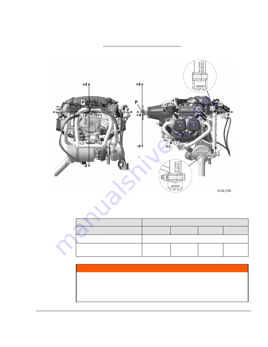
Figure 5.8: Attachment points
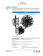
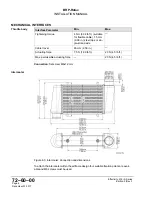
MECHANICAL INTERFACES
Attachment
points
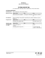
Interface Parameter
Value
Attachment points
L2
R2
L3
R3
x-axis
(in)
615 mm (24.21 in.)
y-axis
(in)
105 mm
(-4.13 in.)
-105 mm
(-4.13 in.)
-105 mm
(-4.13 in.)
-105 mm
(-4.13 in.)
m
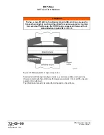
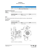
WARNING
Non-compliance can result in serious injuries or death!
The aircraft or fuselage manufacturer must design the engine suspension so that it can
safely carry the maximum occurring operational loads without exceeding the max. al-
lowable forces and bending moments on the engine housing and attachment points.
Tighten all engine suspension screws as specified by the aircraft manufacturer.
Effectivity: 915 i A Series
Edition 0/Rev. 0
Page 9
December 01 2017
Содержание 915 iS 3 A
Страница 10: ...Notes Page 4 December 01 2017 Effectivity 915 i A Series Edition 0 Rev 0 NOTES BRP Rotax INSTALLATION MANUAL ...
Страница 30: ...Notes Page 18 December 01 2017 Effectivity 915 i A Series Edition 0 Rev 0 NOTES BRP Rotax INSTALLATION MANUAL ...
Страница 38: ...Notes Page 8 December 01 2017 Effectivity 915 i A Series Edition 0 Rev 0 NOTES BRP Rotax INSTALLATION MANUAL ...
Страница 82: ...Notes Page 10 December 01 2017 Effectivity 915 i A Series Edition 0 Rev 0 NOTES BRP Rotax INSTALLATION MANUAL ...
Страница 108: ...Notes Page 14 December 01 2017 Effectivity 915 i A Series Edition 0 Rev 0 NOTES BRP Rotax INSTALLATION MANUAL ...
Страница 138: ...Notes Page 6 December 01 2017 Effectivity 915 i A Series Edition 0 Rev 0 NOTES BRP Rotax INSTALLATION MANUAL ...
Страница 162: ...Notes Page 8 December 01 2017 Effectivity 915 i A Series Edition 0 Rev 0 NOTES BRP Rotax INSTALLATION MANUAL ...
Страница 165: ......