


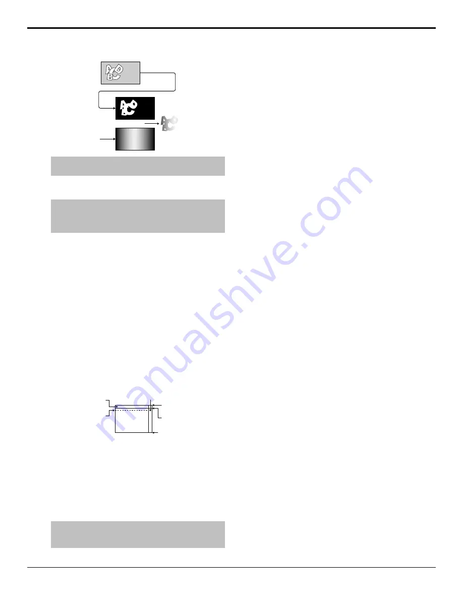
Program E
(background)
Alpha
Video
(fill)
Auto Key
Tip:
You must set up the auto key with the configurable program
output as the alpha and whatever source you want as the fill.
To Set an ME to Layer Mode
Note:
The layer mode output is only fed out of the configurable
program output that is set to Layer Mode. The Program A layer
mode output is fed out of the Program E output and the Program
B layer mode output is fed out of the Program F output.
1.
Press the
SEL
button on the panel row you want to
set the ME Mode for.
2.
Press
ME Modes
.
3.
Select the ME Layer Mode you want to use.
•
Program X
— selected ME operates normally.
•
Layer Mode
— combined key alphas that are
included in the configurable program output of
the ME are used as the video source.
Ancillary Data
You can select which lines in the vertical and horizontal
blanking area are stripped or passed, as well which line
the video image starts on. This allows you to protect and
pass information such as embedded audio, or closed
captioning, with the video signal.
Video Image
Vertical
Blanking
Horizontal Blanking
Video
Image
Start
Line 0 (even)
Line 263 (odd)
Line 20 (even)
Line 283 (odd)
Line 262 (even)
Line 525 (odd)
Figure 8: Vertical and Horizontal Blanking Area (480i)
Field and frame line numbers depend on the video format
the switcher is operating in. If the switcher is operating
in a Progressive Scan video format, no even or odd
information is displayed.
Ancillary data parameters are set independently for each
video format. Changing video formats recalls the last
saved parameters for the selected video format.
Tip:
Refer to
on page 37 for
information on setting the ancillary data source for the
MultiViewer outputs.
To Set Up the Ancillary Data
1.
Press
HOME
>
Setup
>
Installation
>
Output
>
More
>
Ancillary Data
.
2.
Use the
Field (Line)
knob to select a particular lines
in the even and odd fields, or the entire horizontal
blanking region, that you want to set up.
3.
Use the
Pass/Strip
knob to select whether to pass
(
Pass
) the data in the selected fields, or strip (
Strip
)
it.
•
Pass
— data is not removed from the video
stream. Use this setting if you have embedded
audio.
•
Strip
— data is removed from the video stream.
4.
Use the
Image Start
knob to select the first lines
of active video. If closed captioning is present in the
video signal, set the
Image Start
to the line after
the closed captioning line.
5.
Press
HOME
>
Confirm
.
SMPTE
®
352 Payload Identification
The SMPTE
®
352 payload identifier is inserted into the
ancillary data and carries information to identify such
things as the video format and scanning method, interface
standard, and aspect ratio for the current video signal.
Some upstream devices will insert this information, and
others may not. This can result in the SMPTE
®
352
payload identifier appearing and disappearing as you
transition between video signals, causing problems for
downstream devices such as monitors.
The SMPTE
®
352 payload identifier is inserted after the
passing or stripping of the ancillary data by the switcher.
To Insert the SMPTE
®
352 Payload Identifier
1.
Press
HOME
>
Setup
>
Installation
>
Output
>
More
>
More
.
2.
Press
SMPTE 352
to select whether the switcher
inserts the SMPTE
®
352 payload identification (
On
),
or do not insert it (
Off
).
Setting SMPTE
®
352 to
Off
does not strip the
SMPTE
®
352 payload identifier that was added by
an upstream device.
MultiViewer
The switcher supports both a multi-headed video
processor MultiViewer and a single-headed input
MultiViewer. Both types of MultiViewer generators
allow you to view up to 20 video sources in one of 41
different grids and include mnemonic source names and
red and green tallies on every box.
Acuity Setup Manual (v9.2) — Video Output Setup •
35
Содержание Acuity 4410AR-020
Страница 1: ...Acuity Setup Manual v9 2...


