Rosen Aviation 0500-101 Скачать руководство пользователя страница 4

Rosen Aviation 


   Digital Wireless Headphone System 

Document Number: 103517 


  Revision: A 
  Date: 11/23/09 

Template: 4.2.3-6-FM; Revision A; 16 May, 2005 

Page 4 of 10  


1. INTRODUCTION 

The Digital Wireless Headphone System consists of a 5.8 GHz transmitter and 5.8 GHz 
headphones. The transmitter features three audio inputs and a pilot microphone input. The pilot 
microphone input will override the other inputs when active. The unit is designed to integrate into 
any entertainment system with analog audio capability. 

This guide describes general configuration information for the Rosen Wireless Headphone 
Transmitter with any audio source equipment to supplement the Outline & Installation Drawing 
(P/N 

0700-010-CD

).  

Note:

 Only trained and qualified personnel should perform installation and service. 

1.1. Unpacking 

The parts shipped with the 5.8 GHz Digital Wireless Transmitter include:


One 5.8 GHz digital audio transmitter (P/N 

0700-010


One connector kit (P/N 

0300-043

The parts shipped with the 5.8 GHz Digital Wireless Headphones include: 


One set of 5.8 GHz Digital Wireless Headphones (P/N 

0500-101


Two AA batteries (P/N 

BAT-AA


Drawings available a

www.rosenaviation.com

. 

From the 

Rosen Aviation

 home page, select 

Support


Drawings and Pinouts

, and then look 

in the drawings table for the Wireless Transmitter. 

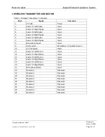
2. CONNECTING THE TRANSMITTER 

The transmitter provides interfaces to connect three audio sources and the pilot microphone. Use 
the pinout descriptions on page 2 of the Outline & Installation drawing to assist in the wiring 
process. Pay close attention to the pinout information while completing wiring connections. 
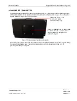
Note:

  The wireless transmitter and headphones are for entertainment purposes only; connect the 

transmitter to the non-critical power bus. 


Содержание 0500-101

Страница 1: ...Document Number 103517 Rev B ELECTRONIC REVISION CONTROLLED...

Страница 2: ...ated into any language in any form by any means without the written authorization from Rosen Aviation LLC except as allowed under copyright laws Disclaimer of Liability The information contained in th...

Страница 3: ...4 1 1 Unpacking 4 2 CONNECTING THE TRANSMITTER 4 3 WIRELESS TRANSMITTER CONNECTOR 5 4 PLACING THE TRANSMITTER 6 5 INSERTING THE BATTERIES INTO THE HEADPHONES 7 6 OPERATING THE HEADPHONES 8 7 TECHNICAL...

Страница 4: ...and service 1 1 Unpacking The parts shipped with the 5 8 GHz Digital Wireless Transmitter include One 5 8 GHz digital audio transmitter P N 0700 010 One connector kit P N 0300 043 The parts shipped w...

Страница 5: ...Right Signal Input 6 Audio 3 Left Signal Input 7 Audio 3 Right Signal Input 8 Microphone Signal Input 9 PA Override Momentary or Constant Ground 10 28 Volt Return GND 11 Audio 1 Left Return Input 12 A...

Страница 6: ...long as the bulkhead or wall is made of composite or wood material Figure 1 Digital wireless headphone transmitter For acceptable performance the transmitter is to be mounted so that the antenna is al...

Страница 7: ...he battery by pressing the bottom of the battery down against the spring at the bottom of the battery compartment The battery should snap into place 3 To remove the battery pull the top of the battery...

Страница 8: ...ces are available After each use be sure to switch off the headphones to extend battery life When the headphones detect no signal for more than one minute the headphones will power off and the LED ind...

Страница 9: ...rve B N A Magnetic Effect 15 0 Z Z Power Input 16 0 Z B N A Voltage Spike 17 0 A N A Audio Frequency Conducted Susceptibility Power Inputs 18 0 Z N A Induced Signal Susceptibility 19 0 AC AC Radio Fre...

Страница 10: ...gnal within the aircraft cabin 9 REGULATORY APPROVALS 9 1 FCC Part 15 Requirements FCC ID PMJTRO2 This device complies with Part 15 of the FCC rules Operation is subject to the following two condition...

Отзывы: