background image

Device functions

Page 55

UPT-6011

Version 5

Slowly increase the correction factor, starting either with the lowest value (50%) or with the value recommended
in the ROPEX Application Report minus 25%, until the actual temperature at the end of the heating impulse cor-
responds to the set temperature.
The correction factor should be checked, and if necessary corrected, whenever the machine is operated or the set
temperature or the sealing time is changed.

8.7.10 Maximum start temperature

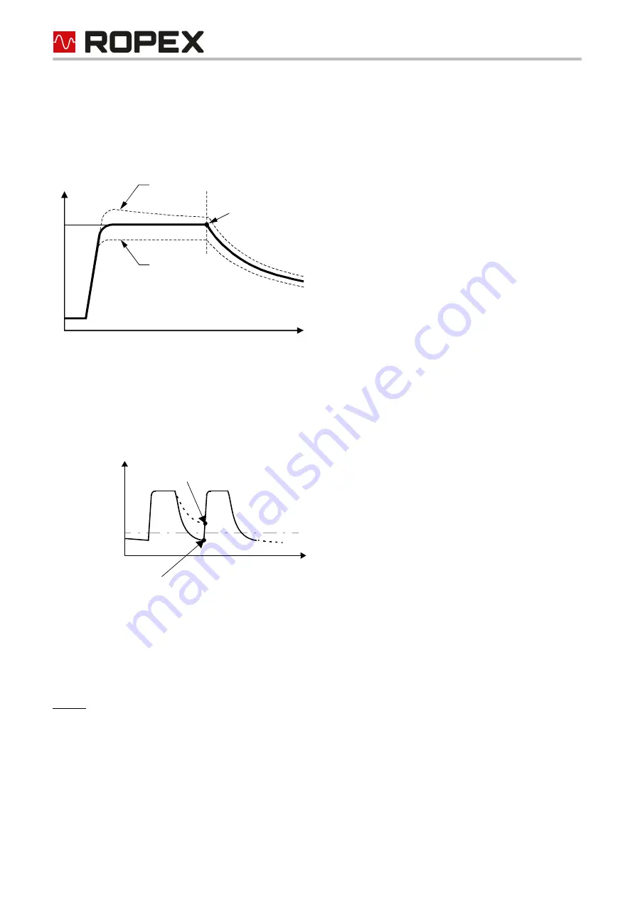
You can set the required maximum start temperature in the parameter data. This temperature is the maximum
allowable actual value at the start time. The value is determined by the controller at the start of each impulse and
compared with the set value.
This function serves to monitor the cooling circuit.

If the cooling system is intact, curve 1) applies. If the cooling system is faulty, curve 2) applies instead because
the water is no longer cooled. The temperature never falls below the value set with this menu step. In this case,
the controller ignores the next heatup command. Error code 305 appears and the alarm relay is switched
(

section 8.19 "Error messages" on page 67). The idea is to prevent the UPT sealing bar from being destroyed.

The maximum value of the setting range is limited by the specified maximum value and the set temperature range.
Both values are selected in the parameter data.
Setting:
It is advisable not to set this parameter until you have determined the optimum heatsealing parameters (temper-
ature and cooling time) for production. The start temperature should be set to approximately 50% of the heat-
sealing temperature for the trial run, to enable the optimum working parameters to be established correctly.

8.7.11 Temperature diagnosis

An additional temperature diagnosis can be activated in the parameter data (EDS file). The UPT-6011 checks
whether the actual temperature is within a settable tolerance band ("OK" window) either side of the set tempera-

Temp.

Time

x

x

Hold value

Co too large

Co too small

T

set

Set start

Time

temperature

Temperature

2)

1)

Start temperature if cooling 

system faulty

Start temperature if cooling system OK

Содержание CIRUS UPT-6011

Страница 1: ...nt features Complete control via EtherNet IPTM interface 2 x RJ 45 Automatic zeroing AUTOCAL Automatic configuration of the secondary voltage and current range AUTORANGE Automatic frequency adaptation Booster output standard Analogue output 0 10 VDC for ACTUAL temperature Alarm function with error diagnosis Heating element alloy and temperature range can be selected Cooling system monitored Wide v...

Страница 2: ...iew of the device 17 7 2 Device configuration 17 7 3 Heating element 19 7 4 Commissioning rules 20 8 Device functions 22 8 1 LEDs and controls 22 8 2 EtherNet IPTM communication 23 8 3 Device description file EDS 23 8 4 Communication protocol 24 8 5 Input data 24 8 6 Output data 27 8 7 Parameter object class 0x0F 31 8 8 Integrated web server 59 8 9 Undervoltage detection 62 8 10 Temperature meter ...

Страница 3: ...age 76 4 Extension of parameter object Restart delay after Reset instance 79 section 8 7 Parameter object class 0x0F on page 31 New section 8 7 14 Restart delay after Reset on page 58 Extension of parameter object with instances 80 and 81 for the TCR Calculator section 8 7 Parameter object class 0x0F on page 31 New section 8 7 2 TCR Calculator on page 53 New Voltage supply range changed to max 480...

Страница 4: ...g element electrical wiring transformer etc will overheat This is the personal responsibility of the user 2 3 Heating element The temperature coefficient of a CIRUS Temperature Controller is specially adapted to CIRUS heating elements The CIRUS Temperature Controller is not allowed to be operated with any other heatsealing ele ments because they could be overheated and damaged beyond repair 2 4 Im...

Страница 5: ...at the device itself complies with the above mentioned standards It does not imply however that the overall system also fulfills these standards It is the responsibility of the machine manufacturer and of the user to verify the completely installed wired and operationally ready system in the machine with regard to its conformity with the safety provisions and the EMC directive see also section Pow...

Страница 6: ... its original carton After transport perform a visual inspection for possible damage 2 10 Disposal This device is subject to Directive 2012 19 EU concerning the reduction of the increasing amount of waste electrical and electronic equipment and the disposal of such waste in an environmentally sound way To guarantee proper disposal and or the recover of reusable material please take the device to a...

Страница 7: ...y vary significantly in terms of performance and physical dimensions All information provided by us in connection with the line filter is merely intended as a guide and is based on a typical measuring setup It serves to demonstrate that compliance with the EMC directive can be achieved by using a line filter that is suitable for the overall system The line filter and current transformer must howev...

Страница 8: ...The main application area is sealing or cutting of thermoplastics using the thermal impulse process The most common application areas are vertical and horizontal form fill seal machines VFFS and HFFS bagging filling and sealing machines bag production machines foil welding devices foil splicer etc 4 System description Sample depiction The basic design of the overall system is shown in the diagram ...

Страница 9: ...ller has an optimized control algorithm as well as numerous functions tailored to specific tasks such as AUTOCAL ALARM with error diagnosis etc These are described in detail below 5 Device features The CIRUS Temperature Controller UPT 6011 is equipped with a EtherNet IPTM interface Through this interface all functions and parameters can be parameterised by means of the higher level machine control...

Страница 10: ...orized persons who have received suitable instruction and are familiar with the associated risks and warranty provisions The supply voltage to the machine side must lie within the permitted voltage and frequency range of the CIRUS Temperature Controller Otherwise there is the danger of a defect 6 1 Installation notes 1 Please refer to the safety and warning notes General information on page 3 2 Th...

Страница 11: ...ked should be used in installations conforming to UL standards If one such device is not adequate for the heatsealing application two separate overcurrent protective devices should be provided one for the controller and one for the application ROPEX Application Report The overcurrent protective device must be located directly adjacent to the controller The minimum possible specification for this d...

Страница 12: ...es load side CIRUS Temperature Controller Relay Kb Load break all pole e g in combination with the alarm output of the temp controller ROPEX recommendation When using a series resistor RV 1 the relay Kb shall be installed Impulse Transformer Designed according to EN 61558 isolating transformer with reinforced insulation Connect core to ground Use transformers with a one section bobbin The power du...

Страница 13: ...n Report calculated for your particular heatsealing application For more technical information Line filter documentation It is permissible to supply several CIRUS control loops with a single line filter providing the total current does not exceed the maximum current of the filter The wiring instructions contained in section 6 3 Power supply on page 12 must be observed Example drawing for LF 06480 ...

Страница 14: ...ounting on DIN rail 35 x 7 5 mm or 35 x 15 mm EN 50022 If the high current wire cannot be routed through the opening provided an HCB 1 high current rail must be used Snap on for DIN rail 35 x 7 5 mm or 35 x 15 mm EN 60715 terminal block terminal wires 14 60 24 75 14 23 28 26 39 12 ...

Страница 15: ...ormer Heating element LINE sec U2 prim U1 Line filter 8 7 5 4 6 3 2 1 Termination RX RX TX Ethernet PORT 1 RJ45 TX Ethernet PORT 2 RJ45 for assignment see PORT 1 Shield ALARM OUTPUT max 30 V Ground Must be grounded externally to prevent electrostatic charging C ATR _ ANALOG OUTPUT 0 10 VDC BOOSTER OUTPUT Current transformer V V 24 VDC POWER SUPPLY twisted UPT 6011 ...

Страница 16: ...N OUT 1 3 Line filter NC NC 14 13 12 7 5 Ethernet module 18 17 6 8 7 5 4 6 3 2 1 Termination RX RX TX Ethernet PORT 1 RJ45 TX Ethernet PORT 2 RJ45 for assignment see PORT 1 Shield ALARM OUTPUT max 30 V Ground Must be grounded externally to prevent electrostatic charging C ATR _ ANALOG OUTPUT 0 10 VDC Heating element sec U2 prim U1 twisted Max length 1m 2 4 V V 24 VDC POWER SUPPLY UPT 6011 ...

Страница 17: ...tion AUTOCAL The voltage is configured in the range from 0 4 VAC to 120 VAC and the current in the range from 30 A to 500 A If the voltage and or current are outside of the permissible range a detailed error message appears on the controller section 8 19 Error messages on page 67 If the secondary current I2 is less than 30 A the secondary high current wire must be laid twice or several times throu...

Страница 18: ...ware tool e g Rockwell s BOOT P DHCP Server or by manually accessing the TCP IP object These settings are stored in the controller However when the power supply to the controller is momentarily interrupted the stored values are only used if the rotary coding switches are set to 00 All other switch positions cause the stored values to be temporarily overwritten Rotary coding switch IP address 00 DH...

Страница 19: ...e controller must be calibrated for it The CIRUS Temperature Controller is suitable for temperature coefficients in the range 400 4000 ppm K The base resistance of the heating element increases continuously during operation owing to the design The AUTOCAL function must therefore be run again approximately every 100 000 heat sealing cycles in order to prevent ACTUAL temperature measuring errors 7 3...

Страница 20: ...ase check the controller configuration before continuing the startup procedure 7 One of the following states then appears 8 Activate the AUTOCAL function while the heating element is still cold by setting the AC bit AUTOCAL in the EtherNet IPTM protocol section 8 4 Communication protocol on page 24 The yellow AUTOCAL LED lights up for the duration of the calibration process approx 10 15 s The AA b...

Страница 21: ...correctly If an error code is displayed proceed as described in section 8 19 Error messages on page 67 10 Optimize the heating and control process either by adjusting the correction factor Co in the parameter data EDS file or using the parameter object section 8 7 9 Correction factor Co on page 54 Any production related resistance tolerances of the heating element are compensated in this way ...

Страница 22: ... TX yellow LED green LED LINK Lit or blinking if Ethernet frames are transmitted Lit if connection exists to Ethernet OUTPUT green LED HEAT ALARM Red LED AC yellow LED yellow LED Lit or blinking to indicate fault Indicates pulses in measurement mode In control mode luminous intensity is proportional to heating current Lit while AUTOCAL process is executing Lit during heating phase red green µC POW...

Страница 23: ... device description file EDS and use this information to create a parameter set for the EtherNet IPTM scanner which controls user data traffic The ROPEX_UPT 6011_V2_5 eds file of the UPT 6011 contains all essential controller information for the configura tion e g the I O data description parameter descriptions etc The device description files and the associated image files BMP and ICO can be requ...

Страница 24: ...orm the low byte and bits 8 15 the high byte INTEL format The 2 x 16 bit input data contains the set point in word and the control functions in word The 3 x 16 bit output data contains the actual value in word the status information in word and the error code in word 8 5 Input data The term input data refers to the data that is transferred from the EtherNet IPTM scanner to the UPT 6011 It con tain...

Страница 25: ... 10 15 seconds The heating element is not heated during this period The yellow LED on the front panel lights up while the AUTOCAL function is executing and the controller shows AUTOCAL active AA bit 1 in the output data The actual value output terminals 17 18 changes to 0 3 C corresponds to approx 0 VDC If the temperature of the heating element fluctuates the AUTOCAL function is executed a maximum...

Страница 26: ...ue output changes to 0 3 C i e approximately 0 VDC and the SA bit is set in order to set the RS bit The AUTOCAL function is not cancelled if the RS bit is set while it is executing The controller performs an internal initialization lasting approximately 500 ms after the RS bit is reset The next heatsealing process cannot be started until it has finished If a Kb contactor is used to deactivate the ...

Страница 27: ...he channel can remain set to 0 In this case the temper ature controller behaves in exactly the same way as older models where different calibration data records are not supported It is possible to switch to another channel during the AUTOCAL function however the controller continues working with the original channel until the AUTOCAL function has finished The channel currently being used by the co...

Страница 28: ...ct Tset factory setting The TO bit is set if the actual value is inside the specified temperature tolerance band If the actual temperature is outside of the tolerance band the TO bit is reset see graph below Unlike the Temperature achieved status bit TE bit the actual temperature is evaluated independently of the control mode 3 Active when Tact Tset with latch function A heatsealing cycle starts w...

Страница 29: ... the line voltage are switched on The SA bit becomes active when the RS bit reset or the MP bit measurement pause are set to 1 handshake procedure In this way the control detects when the controller has accepted the RS bit or the MP bit The tem perature controller can then delete the RS bit or the MP bit again The controller waits for line voltage The following prerequisite must be fulfilled for t...

Страница 30: ...n RS bit 0 SA bit 0 AL bit 0 No reset no standby active no alarm The sealing process is possible 4 On Off RS bit 0 SA bit 0 AL bit 1 No reset no standby active alarm active Error code 201 The line voltage is missing 5 On On RS bit 0 SA bit 0 AL bit 1 no reset no standby active alarm active Error code 201 Line voltage is present but the alarm is not acknowledged 6 On On RS bit 1 SA bit 1 AL bit 1 R...

Страница 31: ...he third word at bit positions 0 9 section 8 19 Error messages on page 67 8 7 Parameter object class 0x0F In accordance with the CIP specification the UPT 6011 provides a parameter object containing all of the device parameters All instances of the parameter object support the Get_Attribute_Single and Get_Attribute_All services The class instance 0 additionally supports the Save Restore and Reset ...

Страница 32: ...NT Temperature range alloy 10 0 4 9 10 11 8 7 1 2 USINT Link path length 6 3 EPATH Link path 20 0F 24 01 30 01 4 WORD Descriptor 0x0000 5 USINT Data type 0xC6 6 USINT Data length 1 2 1 USINT Low temperature OK threshold 10 K 3 99 K 2 USINT Link path length 6 3 EPATH Link path 20 0F 24 02 30 01 4 WORD Descriptor 0x0000 5 USINT Data type 0xC6 6 USINT Data length 1 3 1 USINT High temperature OK thres...

Страница 33: ...k path 20 0F 24 05 30 01 4 WORD Descriptor 0x0004 scaling supported 5 USINT Data type 0xC7 6 USINT Data length 2 13 USINT Factor 1 14 USINT Divisor 100 15 USINT Base 1 16 USINT Offset 0 6 1 USINT Measuring impulse duration 1 7 ms 17 1 7 3 0 ms 17 30 2 USINT Link path length 6 3 EPATH Link path 20 0F 24 06 30 01 4 WORD Descriptor 0x0004 scaling supported 5 USINT Data type 0xC6 6 USINT Data length 1...

Страница 34: ... Link path 20 0F 24 08 30 01 4 WORD Descriptor 0x0000 5 USINT Data type 0xC7 6 USINT Data length 2 9 1 UINT Maximum start temperature 100 20 500 C 2 USINT Link path length 6 3 EPATH Link path 20 0F 24 09 30 01 4 WORD Descriptor 0x0000 5 USINT Data type 0xC7 6 USINT Data length 2 10 1 UINT Temperature coefficient 1700 ppm K 400 4000 ppm K 2 USINT Link path length 6 3 EPATH Link path 20 0F 24 0A 30 ...

Страница 35: ...USINT Data type 0xC7 6 USINT Data length 2 13 1 BOOL Temperature diagnosis Off 0 Off 0 on 1 2 USINT Link path length 6 3 EPATH Link path 20 0F 24 0D 30 01 4 WORD Descriptor 0x0000 5 USINT Data type 0xC1 6 USINT Data length 1 14 1 UINT Temperature diagnosis delay 10 ms steps 0 s 0 999 0 9 99 s 2 USINT Link path length 6 3 EPATH Link path 20 0F 24 0E 30 01 4 WORD Descriptor 0x0004 scaling supported ...

Страница 36: ...16 USINT Offset 0 16 1 USINT Temperature OK bit Active when Tact Tset Off 0 active when Tact Tset 1 active when Tact Tset with latch 2 2 USINT Link path length 6 3 EPATH Link path 20 0F 24 10 30 01 4 WORD Descriptor 0x0000 5 USINT Data type 0xC6 6 USINT Data length 1 17 1 USINT Hold mode Off Off 0 on 1 2 s 2 2 USINT Link path length 6 3 EPATH Link path 20 0F 24 11 30 01 4 WORD Descriptor 0x0000 5 ...

Страница 37: ...emperature coefficient channel 1 1700 ppm K 400 4000 ppm K 2 USINT Link path length 6 3 EPATH Link path 20 0F 24 14 30 01 4 WORD Descriptor 0x0000 5 USINT Data type 0xC7 6 USINT Data length 2 21 1 SINT Calibration temperature channel 2 20 C 1 variable 0 40 C 2 USINT Link path length 6 3 EPATH Link path 20 0F 24 15 30 01 4 WORD Descriptor 0x0000 5 USINT Data type 0xC2 6 USINT Data length 1 22 1 UIN...

Страница 38: ...5 1 UINT Correction factor channel 3 100 25 200 2 USINT Link path length 6 3 EPATH Link path 20 0F 24 19 30 01 4 WORD Descriptor 0x0000 5 USINT Data type 0xC7 6 USINT Data length 2 26 1 UINT Temperature coefficient channel 3 1700 ppm K 400 4000 ppm K 2 USINT Link path length 6 3 EPATH Link path 20 0F 24 1A 30 01 4 WORD Descriptor 0x0000 5 USINT Data type 0xC7 6 USINT Data length 2 27 1 SINT Calibr...

Страница 39: ...Calibration temperature channel 5 20 C 1 variable 0 40 C 2 USINT Link path length 6 3 EPATH Link path 20 0F 24 1E 30 01 4 WORD Descriptor 0x0000 5 USINT Data type 0xC2 6 USINT Data length 1 31 1 UINT Correction factor channel 5 100 25 200 2 USINT Link path length 6 3 EPATH Link path 20 0F 24 1F 30 01 4 WORD Descriptor 0x0000 5 USINT Data type 0xC7 6 USINT Data length 2 32 1 UINT Temperature coeffi...

Страница 40: ...emperature coefficient channel 6 1700 ppm K 400 4000 ppm K 2 USINT Link path length 6 3 EPATH Link path 20 0F 24 23 30 01 4 WORD Descriptor 0x0000 5 USINT Data type 0xC7 6 USINT Data length 2 36 1 SINT Calibration temperature channel 7 20 C 1 variable 0 40 C 2 USINT Link path length 6 3 EPATH Link path 20 0F 24 24 30 01 4 WORD Descriptor 0x0000 5 USINT Data type 0xC2 6 USINT Data length 1 37 1 UIN...

Страница 41: ...th 2 40 1 TIME_O F_DAY Time milliseconds since 00 00 00 00 00 00 2 USINT Link path length 6 3 EPATH Link path 20 0F 24 28 30 01 4 WORD Descriptor 0x0000 5 USINT Data type 0xCE 6 USINT Data length 4 41 1 UDINT Operating hours 0 0 9999999 9 h 2 USINT Link path length 6 3 EPATH Link path 20 0F 24 29 30 01 4 WORD Descriptor 0x0014 5 USINT Data type 0xC8 6 USINT Data length 4 42 1 UDINT Cycle counter n...

Страница 42: ...45 1 UDINT Cycle counter channel 1 0 0 99999999 2 USINT Link path length 6 3 EPATH Link path 20 0F 24 2D 30 01 4 WORD Descriptor 0x0000 5 USINT Data type 0xC8 6 USINT Data length 4 46 1 UDINT Cycle counter channel 2 0 0 99999999 2 USINT Link path length 6 3 EPATH Link path 20 0F 24 2E 30 01 4 WORD Descriptor 0x0000 5 USINT Data type 0xC8 6 USINT Data length 4 47 1 UDINT Cycle counter channel 3 0 0...

Страница 43: ...h 4 50 1 UDINT Cycle counter channel 6 0 0 99999999 2 USINT Link path length 6 3 EPATH Link path 20 0F 24 32 30 01 4 WORD Descriptor 0x0000 5 USINT Data type 0xC8 6 USINT Data length 4 51 1 UDINT Cycle counter channel 7 0 0 99999999 2 USINT Link path length 6 3 EPATH Link path 20 0F 24 33 30 01 4 WORD Descriptor 0x0000 5 USINT Data type 0xC8 6 USINT Data length 4 52 1 INT Start temperature 99 99 5...

Страница 44: ...ation deviation channel 1 0 100 00 100 00 2 USINT Link path length 6 3 EPATH Link path 20 0F 24 37 30 01 4 WORD Descriptor 0x0010 5 USINT Data type 0xC3 6 USINT Data length 2 56 1 INT Calibration deviation channel 2 0 100 00 100 00 2 USINT Link path length 6 3 EPATH Link path 20 0F 24 38 30 01 4 WORD Descriptor 0x0010 5 USINT Data type 0xC3 6 USINT Data length 2 57 1 INT Calibration deviation chan...

Страница 45: ...1 INT Calibration deviation channel 6 0 100 00 100 00 2 USINT Link path length 6 3 EPATH Link path 20 0F 24 3C 30 01 4 WORD Descriptor 0x0010 5 USINT Data type 0xC3 6 USINT Data length 2 61 1 INT Calibration deviation channel 7 0 100 00 100 00 2 USINT Link path length 6 3 EPATH Link path 20 0F 24 3D 30 01 4 WORD Descriptor 0x0010 5 USINT Data type 0xC3 6 USINT Data length 2 62 1 USINT Passes throu...

Страница 46: ...5535 0 6553 5 m 2 USINT Link path length 6 3 EPATH Link path 20 0F 24 40 30 01 4 WORD Descriptor 0x0014 scaling supported 5 USINT Data type 0xC7 6 USINT Data length 2 13 USINT Factor 1 14 USINT Divisor 10 15 USINT Basis 1 16 USINT Offset 0 65 1 UINT Calibration resistance channel 2 in 0 1 m 0 m 0 65535 0 6553 5 m 2 USINT Link path length 6 3 EPATH Link path 20 0F 24 41 30 01 4 WORD Descriptor 0x00...

Страница 47: ...5535 0 6553 5 m 2 USINT Link path length 6 3 EPATH Link path 20 0F 24 43 30 01 4 WORD Descriptor 0x0014 scaling supported 5 USINT Data type 0xC7 6 USINT Data length 2 13 USINT Factor 1 14 USINT Divisor 10 15 USINT Basis 1 16 USINT Offset 0 68 1 UINT Calibration resistance channel 5 in 0 1 m 0 m 0 65535 0 6553 5 m 2 USINT Link path length 6 3 EPATH Link path 20 0F 24 44 30 01 4 WORD Descriptor 0x00...

Страница 48: ... 0 6553 5 m 2 USINT Link path length 6 3 EPATH Link path 20 0F 24 46 30 01 4 WORD Descriptor 0x0014 scaling supported 5 USINT Data type 0xC7 6 USINT Data length 2 13 USINT Factor 1 14 USINT Divisor 10 15 USINT Basis 1 16 USINT Offset 0 71 1 UINT Initial calibration resistance channel 0 in 0 1 m 0 m 0 65535 0 6553 5 m 2 USINT Link path length 6 3 EPATH Link path 20 0F 24 47 30 01 4 WORD Descriptor ...

Страница 49: ... 0 65535 0 6553 5 m 2 USINT Link path length 6 3 EPATH Link path 20 0F 24 49 30 01 4 WORD Descriptor 0x0014 scaling supported 5 USINT Data type 0xC7 6 USINT Data length 2 13 USINT Factor 1 14 USINT Divisor 10 15 USINT Basis 1 16 USINT Offset 0 74 1 UINT Initial calibration resistance channel 3 in 0 1 m 0 m 0 65535 0 6553 5 m 2 USINT Link path length 6 3 EPATH Link path 20 0F 24 4A 30 01 4 WORD Des...

Страница 50: ... 0 65535 0 6553 5 m 2 USINT Link path length 6 3 EPATH Link path 20 0F 24 4C 30 01 4 WORD Descriptor 0x0014 scaling supported 5 USINT Data type 0xC7 6 USINT Data length 2 13 USINT Factor 1 14 USINT Divisor 10 15 USINT Basis 1 16 USINT Offset 0 77 1 UINT Initial calibration resistance channel 6 in 0 1 m 0 m 0 65535 0 6553 5 m 2 USINT Link path length 6 3 EPATH Link path 20 0F 24 4D 30 01 4 WORD Des...

Страница 51: ... 0 79 1 UINT Restart delay after Reset2 0 20 s 0 999 0 9 99 s 2 USINT Link path length 6 3 EPATH Link path 20 0F 24 4F 30 01 4 WORD Descriptor 0x0004 Skalierung unterstützt 5 USINT Data type 0xC7 6 USINT Data length 2 13 USINT Factor 1 14 USINT Divisor 100 15 USINT Basis 1 16 USINT Offset 0 80 1 UINT External measured temperature2 8 7 2 40 40 600 C 2 USINT Link path length 6 3 EPATH Link path 20 0...

Страница 52: ...heir default values This applies to both temporary volatile and retentive objects The Save Restore and Reset services can only be applied to the class instance 0 All instances of the parameter object concerned are simultaneously saved or restored Changes to the instance of the externally measured temperature 80 only have a temporary effect and will not be stored retentively When the controller is ...

Страница 53: ...ontroller and the real temperature of the heatsealing element To calculate the TCR value the temperature at the heatsealing element is measured in control mode ST bit 1 using an external temperature sensor e g a thermocouple The measured temperature is transferred to the tem perature controller in parameter instance 80 The calculated temperature coefficient can be read out from param eter instance...

Страница 54: ...protection against unwanted continuous heating The controller auto matically deactivates the heating impulse after the set heating time limit has elapsed if the start bit remains set for longer than the time specified with this limit The ST bit must be reset before the controller can be started up again The heating time limit is activated by default 5 00 s but can be set to any value between 0 s a...

Страница 55: ...e value set with this menu step In this case the controller ignores the next heatup command Error code 305 appears and the alarm relay is switched section 8 19 Error messages on page 67 The idea is to prevent the UPT sealing bar from being destroyed The maximum value of the setting range is limited by the specified maximum value and the set temperature range Both values are selected in the paramet...

Страница 56: ... be set in the parameter data EDS file The first time the low tolerance limit is exceeded the temperature diagnosis is not activated until the configured delay time has elapsed The tem perature diagnosis function can thus be selectively deactivated e g if the temperature drops temporarily owing to the closure of the sealing jaws The high and low tolerance limits cannot be set in the ROPEX visualiz...

Страница 57: ... ACTUAL temperature is indicated up until the end of the first heating phase 3 2 sec This setting causes the current ACTUAL temperature to be output for an additional 2 seconds by means of the EtherNet IPTM protocol at the end of a heatsealing phase The ACTUAL temperature is then output again in real time until the end of the next heatsealing phase Hold mode only applies to the ACTUAL temperature ...

Страница 58: ...RS bit the CIRUS Temperature Controller waits until any contactor connected has closed the heating circuit again Only after this waiting time has elapsed measuring pulses are generated again in order to determine the current ACTUAL temperature and to carry out error diagnos tics This restart delay is 0 2 s by default and can be adjusted with the parameter instance 79 This allows slower switching c...

Страница 59: ...he top right hand corner The web server uses JavaScript and has been successfully tested with Internet Explorer 9 10 and 11 as well as with Microsoft Edge It also works with the latest version of the Safari and Firefox browsers 8 8 1 Home page This page contains general product information under Device Information for instance the product name serial number firmware version MAC address and real ti...

Страница 60: ...an download and display the device protocol for the temperature controller on this page You see the overall size of the protocol Total event entries as well as the upload progress All entries appear in the form of a table A timestamp generated by the built in clock the operating hours and cycle counters and the channel selected at the time are shown for each entry In addition to errors the protoco...

Страница 61: ... 5 Graphic page The temperature controller has an internal memory which can store temperature curves over a period of up to 5 seconds This memory is automatically filled when the ST bit is set You can display or export the memory con tents on the Graphic page By clicking on Refresh you cause the graphic data to be downloaded from the memory of the temperature con troller and displayed again Clear ...

Страница 62: ...through current transformer are displayed This value can be read or written by means of acyclic services Set this value to the real wire passes through the current transformer for that the absolute resistance values can be calculated correctly This value has no influence on the calculation of the percentual calibration deviation The calculation of the absolute resistance values is liable to variat...

Страница 63: ...ent low line or 24 VDC supply voltage from resulting in defective heatseals 8 10 Temperature meter actual value output The UPT 6011 supplies an analog 0 10 VDC signal which is proportional to the real ACTUAL temperature at terminals 17 18 Voltage values 0 VDC 0 C 10 VDC 300 C or 500 C depending on the device configuration UPT 6011 Actual value output 0 10 VDC 18 17 0 V Temperature meter e g ATR 3 ...

Страница 64: ...urbances to be observed extremely efficiently and interpreted accordingly The same applies if several neighbouring control loops interfere with one another If a fault is signalled this analog output is used to display a selective error message section 8 19 Error mes sages on page 67 8 11 Booster connection The UPT 6011 controller has a connection for an external switching amplifier booster as stan...

Страница 65: ...1 This is a read only counter which cannot be reset It can be displayed in the ROPEX visualization soft ware section 8 12 USB interface for visualization software ROPEXvisual on page 65 via the integrated web server or using the acyclic services of the EtherNet IPTM interface 8 15 Operating hours counter The number of operating hours since the controller was shipped is stored in the internal memor...

Страница 66: ...itched on for at least three hours to make sure the clock s capacitor is fully charged When the controller is switched off the fully charged capacitor can keep the clock running for approximately 2 4 weeks If the controller is switched off for longer the date and time will have to be set again You can do this in the ROPEX visualization software section 8 12 USB interface for visualization software...

Страница 67: ...he START signal is present in one of these states the voltage value does not change any more If a ROPEX temperature meter e g an ATR x is connected to the controller s analog output the temperature indication can be directly assigned to the error codes if an alarm is signalled An error message can be reset by setting the RS bit or by momentarily interrupting the power to the controller 24 VDC supp...

Страница 68: ...areas 107 2 66 Temperature step down Fault areas loose contact Fault areas loose contact 108 Temperature step up 307 Temperature too high low section 8 7 11 308 309 310 201 3 33 No line frequency line fre quency fluctuates Check power supply Check power supply 202 Line frequency too high fluctuates 203 Line frequency too low fluctuates 304 4 00 Heatup time too long section 8 7 12 Perform RESET Per...

Страница 69: ...ne started for first time Action if machine already operated heating element not changed 104 5 33 10 Current signal incorrect incorrect impulse transformer specification Perform AUTOCAL check transformer specifi cation fault areas Fault areas loose contact 105 Voltage signal incorrect incorrect impulse transformer specification 106 Current and voltage signals incorrect incorrect impulse transforme...

Страница 70: ...o calibration possible Fault area check configuration Fault areas loose contact 112 7 33 10 Voltage signal incorrect no calibration possible Fault area check configuration Fault areas loose contact 113 8 00 10 Current voltage signals incor rect no calibration possible Fault area check configuration Fault areas loose contact 114 8 66 10 Temperature fluctuates no calibration possible Perform AUTOCAL...

Страница 71: ...of impulse transformer interrupted No UR signal Measurement cable interrupted Partial short circuit delta R Heating element partially bypassed by conducting part clamp opposite heatsealing bar etc Parallel circuit interrupted Wire break heating element break Contact to heating element is defective Total short circuit Heating element incorrectly installed no insulation at heat sealing bar ends or i...

Страница 72: ...ture range Heatsealing element alloy 1700 ppm K Temperature range 300 C Rotary coding switch 0 position Slide switch for alarm relay Alarm relay energized at alarm Temperature diagnosis Temperature diagnosis Off Heatup timeout Heatup timeout Off Fault area Explanation Possible causes 0 5 1 2 3 4 6 7 8 9 AUX CONFIGURATION ALARM OUTPUT ENERGIZED AT ALARM DE ENERGIZED SWITCH POS 4 0 9 TEMP RANGE 500 ...

Страница 73: ...age Terminals 5 7 24 VDC Imax 200 mA control mode 1 A switch on current Tolerance 10 SELV or PELV supplied from max 300 VAC Cat II Measuring range Secondary voltage UR 0 4 120 VAC Secondary current IR 30 500 A with PEX W4 W5 current transformer ROPEX Application Report EtherNet IPTM inter face 2 Ethernet switch ports RJ45 Wiring IEC 61784 5 3 Data transfer rate 10 or 100 MHz Data transport layer E...

Страница 74: ... e g from other devices and wiring must be allowed when installing the device The moving clip required for fastening must be facing down for mounting on a horizontal top hat rail End holders to mechanically fix the controller must be fitted at both ends for mounting on a vertical top hat rail Weight Approx 0 5 kg incl connector plug in parts Housing material Plastic polycarbonate UL 94 V0 Connecti...

Страница 75: ...ide range of heatsealing applications One modification MOD is available for the CIRUS Temperature Controller UPT 6011 for implementing special applications The modifications must be ordered separately MOD 01 Booster for low secondary voltages UR 0 2 60 VAC This modification is necessary for example for very short or low resistance heating elements 75 0 90 0 113 0 135 0 ...

Страница 76: ... W5 Art no 885107 Monitoring current transformer MSW 2 Art no 885212 Network filter LF 06480 Continuous current 6 A 480 VAC art no 885500 with UL certification 10520 Continuous curr 10 A 520 VAC art no 885504 with UL and CSA certification 35480 Continuous curr 35 A 480 VAC art no 885506 50520 Continuous curr 50 A 520 VAC art no 885509 with UL and CSA certification Impulse transformer For design an...

Страница 77: ...der Page 77 UPT 6011 Version 5 Booster B 075415 Impulse loaded 75 A 415 VAC art no 885302 100400 Impulse loaded 100 A 400 VAC art no 885304 Lines For design and order specifications see ROPEX applica tion report ...

Страница 78: ...rotection 74 Device description file EDS 23 Dimensions 75 Disposal 6 E EDS file 23 Error code format 55 Error diagnosis 9 Error messages 67 EtherNet IP interface 73 External switching amplifier 16 F Factory settings 72 Fault 27 Fault areas 71 Fuse 12 H Heating element 4 19 Heating element type 73 Heatup timeout 56 I Impulse transformer 4 12 76 Input data 24 Installation 10 74 Installation procedur...

Страница 79: ...is 65 System monitoring 66 T TCR 19 TCR Calculator 53 TE bit 28 Temperature achieved 28 Temperature coefficient 19 Temperature diagnosis 55 56 Temperature meter 64 76 Temperature OK 28 Temperature range 18 73 Thermal impulse process 8 Time 66 Timestamp 66 TO bit 28 Transformer 4 12 76 Transportation 6 Type of construction 73 U UL file 74 USB interface 65 V View of the device 17 Visualization softw...

Отзывы: