Operation
Lifter
253 / 564
6.14.2
Depth guide
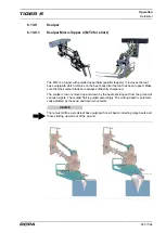
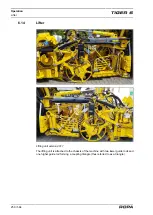
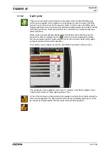
There are seven depth-control wheels on the depth-control shaft at the lifting unit.
As the name suggests, these wheels are not supposed to bear the load of the lifter,
but just to serve as sensors for the ground surface. For this reason, the lifting unit is
largely supported by the two three-point cylinders located between the chassis and the
main lifting unit frame. These two cylinders are controlled via an electronically regu-
lated valve block.
Depth control is automatically activated when the depth-control shaft touches the
ground. The R-Touch displays the icon . If the machine is stopped during lifting,
then the automated system stops operation. When the machine starts driving again,
automatic depth-control restarts operation.
The hectare counter always records the area lifted when depth control is active.
additional topper lifting
row distance (mm)
limit rollers
lifter up + multifunction
single-row automatic stage
attachment (lifter/defoliator)
Off
depth-control stage
500
5
50OFF
AUTO
5
5
lifter side shift
AUTO
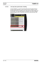
The sensitivity of the regulation can be set in 10 stages in the "Main settings" menu,
"Attachment" submenu, "Step depth guidance" line.
If one of the two staying close warning icons appears on the R-Touch while raising the
three-point suspension, the depth-control roller cannot completely swing down. It can
be caused by foreign objects near the depth-control shaft suspension.
Содержание Tiger 6
Страница 3: ...Contents 3 564 Contents...
Страница 4: ...Contents 4 564...
Страница 13: ...Preface 13 564 1 Preface...
Страница 14: ...Preface 14 564...
Страница 22: ...Safety 22 564...
Страница 23: ...Safety 23 564 2 Safety...
Страница 24: ...Safety 24 564...
Страница 41: ...General View and Specifications 41 564 3 General View and Specifications...
Страница 42: ...General View and Specifications 42 564...
Страница 53: ...General Description 53 564 4 General Description...
Страница 54: ...General Description 54 564...
Страница 57: ...Operating Components 57 564 5 Operating Components...
Страница 58: ...Operating Components 58 564...
Страница 63: ...Operating Components Driver s cabin overview 63 564 13 14 15 13 First aid box 14 Blow gun 15 USB interface...
Страница 98: ...Operation 98 564...
Страница 99: ...Operation 99 564 6 Operation...
Страница 100: ...Operation 100 564...
Страница 226: ...Operation Defoliator 226 564 RIS defoliator RES defoliator...
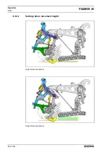
Страница 256: ...Operation Lifter 256 564 6 14 4 Setting rollers movement height High rollers movement High rollers movement...
Страница 291: ...Operation Infeed conveyor 291 564 2 1 1 Infeed conveyor control block...
Страница 299: ...Operation Strainer wheels turbines 299 564 4 Rpm strainer wheels...
Страница 325: ...Operation Bunker unloading 325 564 6 19 Bunker unloading...
Страница 327: ...Operation Bunker unloading 327 564 45 51 50 47 46 52 53 54 48 55 49 56 Key overview See Page 88...
Страница 361: ...Maintenance and Service 361 564 7 Maintenance and Service...
Страница 362: ...Maintenance and Service 362 564...
Страница 418: ...Maintenance and Service Defoliator 418 564 Defoliator in the maintenance position...
Страница 475: ...Malfunction and Remedies 475 564 8 Malfunction and Remedies...
Страница 476: ...Malfunction and Remedies 476 564...
Страница 527: ...Lists Tables Plans Diagrams Maintenance Verification 527 564 9 Lists Tables Plans Diagrams Maintenance Verification...
Страница 528: ...Lists Tables Plans Diagrams Maintenance Verification 528 564...
Страница 558: ...558 564...
Страница 559: ...Index 559 564 10 Index...
Страница 560: ...Index 560 564...

