
IV.
OPERATION INSTRUCTION:
1. DC Voltage Measurement V(DCV):
1.1 Connect RED test lead to “V mA” jack, BLACK test lead to “COM” jack.
1.2 Set the FUCTION switch to the desired V(DCV) position. If not sure, set to the
highest range.
1.3 Connect the test leads across the source or load under measurement.
2
. DC Current Measurement A (DCA):
2.1 Connect the RED test lead to “V mA” jack when the current is less that 200 mA
and to “10A” jack when the current is larger than 200 mA. Connect the BLACK test
lead to the “COM” jack. Set the FUNCTION switch to the desired DCA position.
Connect the test leads across the source or load under measurement.
3. AC Voltage Measurement V (ACV):
3.1 Connect the RED test lead to “V mA” jack and BLACK test lead to the “COM” jack.
3.2 Set the FUCTION switch to the desired ACV position
3.3 Connect the test leads across the source or load under measurement.
4. Resistance Measurement:
4.1 Connect the RED test lead to “V mA” jack and BLACK test lead to “COM” jack.
4.2 Set the FUNCTION switch to the OHM position.
4.3 Connect the test leads across the resistor under measurement.
4.4 When measuring the resistance, the power should be turned off and in short circuit
staues by connecting the two test leads.
5. Transistor hFE Measurement:
5.1 Set the FUNCTION switch to the hFE position.
5.2 Insert the E.B.C. of the PNP or NPN transistor to the proper jack in the socket on the
front panel.
6. Diode and Audible Continuity Measurement
6.1 Connect RED test lead to the “V mA” jack and BLACK test lead to the “COM” jack.
6.2 Set the FUNCTION switch to the
position and connect the RED test leads
to the ANODE of diode and BLACK to CATHODE. The display will the show the
approx. Forward voltage of the diode. If connect the test leads on the other way
round, the display will show an overrange status”1”
6.3 Buzzer sounds if the resistance between the two probes less than approximately 70.
7. Battery Test:
7.1 Connect RED test lead to the “V
Ω
mA”jack and BLACK test lead to the “COM” jack.
7.2 Turn the FUNCTION switch to the BATT position. Connect the test lead across the
battery under measurement. The display will show the voltage of the battery.
V.
BATTERY AND FUSE REPLACEMENT:
When the voltage of the battery is low, the symbol “BATT” will appear on
the display. Then the battery should be replaced. You should check the fuse when
no measurement could be taken for current using mA range.
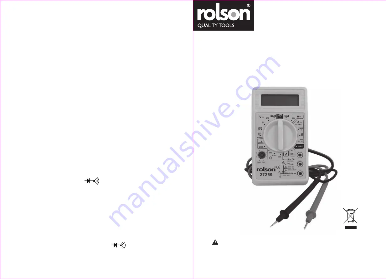
Digital Multimeter
27259
Operating Manual
- 3 -
To Prevent Serious Injury From Accidental Operation:
Turn The Power Switch Of The Tool To Its “Off” Position
And Remove The Test Leads Before Performing Any Inspection,
Maintenance, Or Cleaning Procedures.
WARNING


