background image

29

Audio Operations

Controlling Fader Operation 

Automatically (Auto Mixing)

This automatically controls fader operations that normally are 

performed by an operator (Auto Mixing feature). It lets you rely on 

the XS-62S to perform complex fader operations, enabling use in 

circumstances where no dedicated operator is assigned.
This is especially useful for meetings, discussions, debates, and 

other situations where multiple microphones are used.

MEMO

Auto mixing can independently control the output to the 

PGM/1 bus and the output to the PVW/2 bus.

1. 

Follow the procedure in “Adjusting the Head Amp 

Gain” (p. 25) to adjust the input gain for channels 1 

through 4.

2. 

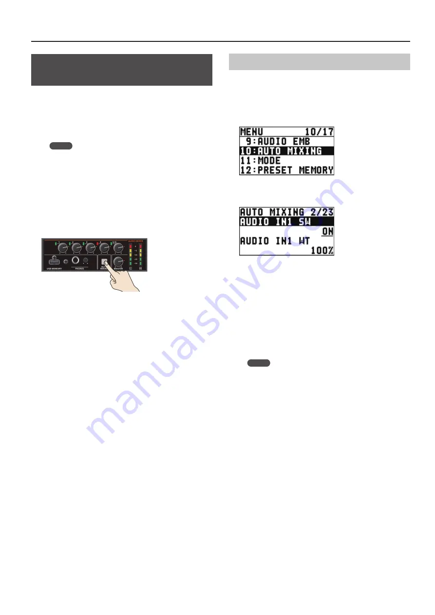
Press the [AUTO MIXING] button to turn on the 

Auto Mixing feature (making the button light up).

3. 

To turn off the Auto Mixing feature, press the [AUTO 

MIXING] button a second time.

Adjusting the Auto Mixing Effect

If you want to adjust the auto mixing volume control to your 

preferred balance, you can make fine adjustments for each input.

1. 

Select the [MENU] button 

“AUDIO AUTO 

MIXING.”

2. 

Select the audio to use with Auto Mixing, then use 

the [VALUE] knob to set it to “ON.”

Set audio where Auto Mixing is not needed, such as background 

music, to “OFF.”

3. 

Press the [VALUE] knob to apply the setting.

4. 

Set “WT” (weight), then use the [VALUE] knob to 

set the priority level for volume-level distribution 

(from 0 to 100%).

If there is audio that you want to make more prominent, 

such as when you want to raise the volume level of an emcee 

microphone, raise the weight level of that audio to emphasize it, 

and lower the weight level for other audio.

MEMO


5

On audio to which Auto Mixing is applied, setting the 

weight level to “0%” results in no audio output.


5

When air-conditioner noise or the like is a concern, set the 

weight level to a low value.

5. 

Press the [VALUE] knob to apply the setting.

Repeat steps 4 through 7 as needed.

6. 

Press the [MENU] button to quit the menu.

Содержание XS-62S

Страница 1: ...d TALLY GPIO 2017 Roland Corporation To obtain the PDF manual 1 Enter the following URL in your computer https proav roland com I 2 Go to the XS 62S product page and click the Support Before using the XS 62S ensure that its system program is at the most recent version For information on available upgrades for the system program see the Roland website https proav roland com You can check the system...

Страница 2: ...use harmful interference and 2 this device must accept any interference received including interference that may cause undesired operation This equipment requires shielded interface cables in order to meet FCC class B limit Any unauthorized changes or modifications not expressly approved by the party responsible for compliance could void the user s authority to operate the equipment For Canada CAN...

Страница 3: ...usting the Volume Balance 26 Selecting the Audio of the Bus to Output 26 Applying Effects to Audio 27 Applying Effects to Input Audio 27 Applying Effects to Output Audio 28 Controlling Fader Operation Automatically Auto Mixing 29 Adjusting the Auto Mixing Effect 29 Silencing Specific Audio Mute 30 Interlinking Audio Output to Video Switching Audio Follow 30 Separating Discrete Analog Input Audio S...

Страница 4: ... 20 cm 8 in 20 cm 8 in WARNING Do not disassemble or modify by yourself Do not carry out anything unless you are instructed to do so in the owner s manual Otherwise you risk causing malfunction Do not repair or replace parts by yourself Refer all servicing to your retailer the nearest Roland Service Center or an authorized Roland distributor as listed on the Information Do not use or store in the ...

Страница 5: ...der IMPORTANT NOTES CAUTION When disconnecting the power cord grasp it by the plug To prevent conductor damage always grasp the power cord by its plug when disconnecting it Periodically clean the power plug An accumulation of dust or foreign objects between the power plug and the power outlet can lead to fire or electric shock At regular intervals be sure to pull out the power plug and using a dry...

Страница 6: ...nal Precautions Any data stored within the unit can be lost as the result of equipment failure incorrect operation etc To protect yourself against the irretrievable loss of data try to make a habit of creating regular backups of the data you ve stored in the unit Roland assumes no liability concerning the restoration of any stored content that has been lost Use a reasonable amount of care when usi...

Страница 7: ...This returns you to the menu one level higher VALUE button Turning This selects a menu item or changes a setting value Pressing This accepts the selected menu item or applies changes to a setting It also executes operations 7 SW MODE button This switches the functioning of the Cross Point 1 8 buttons 8 FREEZE button This stops freezes input video When on this is lit red p 19 9 Cross point 1 8 butt...

Страница 8: ...ion to outputting a list of input output videos or outputting the OSD menu the HDMI OUT 3 connector can also output video at a variety of resolutions p 10 SDI input connector HDMI input connector These connectors input video signals from a computer or video devices such as video cameras and DVD players Channels 5 and 6 are allocated to the respective inputs For channel 6 setting an assigned input ...

Страница 9: ...nnect a USB flash drive to this port You use it when importing still images p 20 or when saving or loading settings for the unit p 34 When using a USB flash drive for the first time you must format it using the XS 62S p 34 Never turn off the power or remove the USB flash drive while the USB flash drive is being accessed RCA phono plug XLR plug AUDIO IN 5 L 6 R jacks These jacks input audio signals...

Страница 10: ...isplays the video of the PGM 1 bus 3 Channel section This displays video input via channels 1 6 and still images assigned to channels 7 and 8 The PGM 1 bus video and PVW 2 bus video are displayed with tally borders Channel Information 1 2 3 1 When the Audio Follow feature is on p 30 the A F symbol is displayed 2 When video or a still image is being sent to the AUX 3 bus p 18 the AUX symbol is disp...

Страница 11: ... SYSTEM 0 set AUTO OFF to OFF NOTE 5 5 Any settings that you are in the process of editing will be lost when the power is turned off If you have any settings that you want to keep you should save them beforehand 5 5 To restore power turn the power on again Operating the Menu This makes menus appear on the built in display for making settings for video and audio or for the XS 62S itself The OSD men...

Страница 12: ...tomatically converted to a progressive signal The picture might appear jagged at this time or the picture in a PinP inset screen or on the multi view monitor might waver This is due to progressive conversion and is not a malfunction About frame rates Frame rates that can be input are 59 94 Hz and 50 Hz Inputting video at a frame rate other than these might result in no output or dropped frames To ...

Страница 13: ...lue INTERNAL EDID information for all inputtable formats is sent 800 x 600 1024 x 768 1280 x 800 1280 x 1024 1366 x 768 1400 x 1050 1600 x 1200 1920 x 1200 720p 3 1080i 3 1080p 3 3 For channel 6 this setting can be made only when INPUT ASSIGN p 13 is set to HDMI 3 Press the VALUE knob to apply the setting 4 Press the MENU button to quit the menu Assigning aVideo Source to Channel 6 You can assign ...

Страница 14: ...is adjusts the display position in the horizontal direction POSITION V 2 This adjusts the display position in the vertical direction BRIGHTNESS This adjusts the brightness CONTRAST This adjusts the contrast SATURATION This adjusts the saturation RED This adjusts the red level GREEN This adjusts the green level BLUE This adjusts the blue level 1 Refer to the About the HDMI OUT 3 Connector p 14 2 Th...

Страница 15: ... 5 connector p 13 1 This is available when SCALING TYPE is set to MANUAL HDMI ANLG IN6 HDMI IN 6 connector 2 RGB CMPNT CMPST IN 6 connector 2 Menu item Explanation INPUT ASSIGN This selects the video signal that is input AUTO SAMPLING 3 This automatically adjusts the image quality FLICKER FILTER Setting this to ON reduces flicker ZOOM This adjusts the zoom ratio SCALING TYPE This sets the scaling ...

Страница 16: ...Output bus assignment Output audio PGM 1 This outputs the audio on the PGM 1 bus PVW 2 This outputs the audio on the PVW 2 bus AUX 3 This outputs the audio on the AUX 3 bus Inputting Copyright protected HDCP Video To input copyright protected HDCP video from a Blu ray Disc player or the like follow the steps described below to change the HDCP setting The XS 62S must be connected to an HDCP compati...

Страница 17: ...ter checking that video output it to the PGM 1 bus 1 Press the SW MODE button several times to make it light yellow The buses selected by the cross point buttons upper row will be the PGM 1 and PVW 2 buses 2 Press a cross point button upper row to select the preset video the video to be output next Lighted in red PGM 1 bus Lighted in green PVW 2 bus The channel you press is lit green Alternatively...

Страница 18: ... p 19 5 5 When the following conditions are satisfied the channels are switched with a black fade effect 5 5 When in MATRIX mode 5 5 When the TRANSITION TYPE is MIX or WIPE 5 5 When the TRANSITION TIME is other than 0 0sec 5 5 In MATRIX mode the TAKE button does nothing Selecting the Channel for Output to the AUX 3 Bus Here s how to select the channel that is output to the AUX 3 bus 1 Press the SW...

Страница 19: ... also use it as a source for DSK compositing p 27 You can save up to two still images in the unit When still images are saved in the unit startup takes longer time according to image size and the number of still images saved Capturing a Still Image from InputVideo This captures a still image from input video and saves it in the unit NOTE 5 5 All video input stops during still image capture 5 5 Dep...

Страница 20: ...TILL IMAGE 4 Use the VALUE knob to select STILL IMAGE1 or STILL IMAGE2 as the memory where the still image is saved A symbol is displayed for memory where a still image is already saved 5 Press the VALUE knob The USB LOAD screen appears The names of the files on the USB flash drive are displayed on this screen 6 Select the still image file you want to import then press the VALUE knob A confirmatio...

Страница 21: ...TILL IMAGE1 or STILL IMAGE2 as the memory you want to delete A symbol is displayed for memory where a still image is already saved 3 Press the VALUE knob A confirmation message appears If you want to cancel the operation press the EXIT button 4 Use the VALUE knob to select YES then press the VALUE knob The still image is deleted 5 Press the MENU button to quit the menu ...

Страница 22: ...set screen and background image are composited and output to the PGM 1 bus The cross point button for the PVW 2 bus light up in red When you press the TAKE button once again you return to the video of only the PGM 1 bus MEMO 5 5 To adjust the position and size of the inset screen make settings in the menu For details refer to Making detailed settings for the inset screen p 22 5 5 The video transit...

Страница 23: ...ton for the PVW 2 bus light up in red When you press the TAKE button once again you return to the video of only the PGM 1 bus MEMO You can specify the split composition pattern For details refer to Specifying a split composition pattern p 23 6 To turn off video composition press the lighted PinP button Specifying a split composition pattern You can specify the split composition pattern to match th...

Страница 24: ...K composited and the mix level of the overall image For details refer to Setting the key type and extraction color p 24 Setting the mix level and effect depth of the composited video p 24 Setting the key type and extraction color To change the key type and extraction color to match the video you want to composite Select the MENU button 0 DSK 0 KEY TYPE then make the settings for the menu items sho...

Страница 25: ...K indicator light up in red SIG PEAK indicator Status Red When input reaches the peak value 0 dB Green When input is detected 50 dB or higher 6 Press the VALUE knob to apply the setting 7 Press the MENU button to quit the menu Adjusting the digital gain On the XS 62S separately from head amp gain you can also adjust digital gain Whereas head amp gain adjusts analog audio digital gain adjusts digit...

Страница 26: ...0 to 6 light up adjust the volume for the speakers or the amplifier Using the MASTER knob to carry out further adjustment might result in distortion or degradation of sound quality MEMO You can output a test tone which is useful for adjusting the volume level Select the MENU button 0 SYSTEM 0 set TEST TONE to 20dB 1kHz 10dB 1kHz or 0dB 1kHz Selecting the Audio of the Bus to Output You can select t...

Страница 27: ...is sets the level used as the threshold at which the compressor is applied Compression is applied to audio that exceeds the threshold COMP RATIO This species the degree of compression applied to the audio The state in which no compression is applied is defined as 1 COMP ATTACK This sets the time until compression starts when audio exceeding the threshold is input COMP RELEASE This adjusts the leng...

Страница 28: ... or attenuates the low band EQ Lo FREQ This adjusts the center frequency when changing the tone quality in the low band Multi band compressor MULTI BAND COMP This applies separate compressors in individual frequency bands Menu item Explanation MB COMP This switches the multi band compressor on and off MB COMP H THLD MB COMP M THLD MB COMP L THLD These set the individual levels that become the thre...

Страница 29: ...uto Mixing Effect If you want to adjust the auto mixing volume control to your preferred balance you can make fine adjustments for each input 1 Select the MENU button 0 AUDIO AUTO MIXING 2 Select the audio to use with Auto Mixing then use the VALUE knob to set it to ON Set audio where Auto Mixing is not needed such as background music to OFF 3 Press the VALUE knob to apply the setting 4 Set WT wei...

Страница 30: ...utomatically and other audio is automatically muted NOTE When the Audio Follow feature is turned on switching between audio output and muting is carried out automatically The position of the knobs that adjust the volume does not change 1 Follow the procedure in Adjusting the Volume Level p 25 to adjust to the volume level you want to output 2 Select the MENU button 0 AUDIO FOLLOW 3 Select the vide...

Страница 31: ...IN 1 5 6 can be added to the SDI connector The HDMI OUT connectors accommodate two channels of embedded audio The assigned bus stereo audio can be added to the HDMI connector The audio shown below is assigned to the respective channels of SDI embedded audio SDI embedded audio channel number Assigned audio Channel 1 The L channel of the bus Channel 2 The R channel of the bus Channel 3 AUDIO IN 1 Ch...

Страница 32: ...audio is sent DRY This sends the source audio with no effects applied WET This sends the effect applied audio 4 Press the VALUE knob to apply the setting Repeat steps 2 through 4 as needed 5 Select SDI OUT1 AUDIO or SDI OUT2 AUDIO then use the VALUE knob to set it to CH1 8 Audio containing channels 3 to 8 of embedded audio is output from the SDI OUT connector set to CH1 8 6 Press the VALUE knob to...

Страница 33: ...re not saved in a preset memory Category Settings saved in the unit REMOTE All menu items LAN SYSTEM All setting items except TEST PATTERN and TEST TONE TEST PATTERN and TEST TONE are always set to OFF at startup Recalling settings This calls up a saved preset When recalling a preset by pre specifying the setting values to call up you can recall just some settings without having to call up all sto...

Страница 34: ... knob to select SAVE then press the VALUE knob A confirmation message appears If you want to cancel the operation press the EXIT button 5 Use the VALUE knob to select YES then press the VALUE knob The file X62 is newly saved on the USB flash drive 6 Press the MENU button to quit the menu MEMO Still images p 19 are not saved in the file X62 Overwrite saving a settings file 1 Select the MENU button ...

Страница 35: ...force Performing formatting 1 Select the MENU button 0 USB MEMORY 0 FORMAT A confirmation message appears If you want to cancel the operation press the EXIT button 2 Use the VALUE knob to select YES then press the VALUE knob Formatting of the USB flash drive is carried out 3 Press the MENU button to quit the menu Returning Settings to the Factory default State Factory Reset You can return the valu...

Страница 36: ...in step 3 are locked 7 To turn off panel lock again press and hold the EXIT button and the MENU button at the same time for 3 seconds or longer The message LOCK RELEASED is displayed and panel lock is turned off Operating the XS 62S or an External Device by Remote Control You can remotely control the XS 62S from a computer or remotely control an externally connected camera Using the dedicated XS 6...

Страница 37: ... pin corresponding to the video channel being output also including video composition and transition effects The tally signal output affects the video of the PGM 1 and PVW 2 buses Roland website For the specifications of the TALLY GPIO connector refer to the Reference Manual PDF available for download at the Roland website https proav roland com ...

Страница 38: ...tors p 16 Is the display connected correctly When outputting copyright protected HDCP video connect an HDCP compatible display p 16 Snowy noise video is output It is possible that the HDMI signal is not being sent and received correctly Reconnect the HDMI cable The colors on the monitor screen connected via HDMI are incorrect Do the color space settings for any monitors connected to the HDMI OUT c...

Страница 39: ... box designed for a condenser mic Other Problems Buttons and knobs cannot be operated Is panel lock turned on When the message OPERATION LOCKED is shown on the built in display panel lock is turned on Press and hold the EXIT button and the MENU button at the same time for 3 seconds or longer to turn off panel lock p 36 A USB flash drive cannot be read Has the USB flash drive been formatted on the ...

Страница 40: ...ALER DSK 7 I P CONV SDI Input 3 FS CONV SDI Input 4 FS I P HDMI Input FS EDID Emu SCALER FREEZE CAPTURE FREEZE CAPTURE FREEZE CAPTURE FREEZE CAPTURE FREEZE CAPTURE 8 STILL IMAGE STILL IMAGE RGB CMPNT CMPST Input EDID Emu PinP SPLIT P I CONV PGM 1 PVW 2 AUX 3 PGM 1 PVW 2 AUX 3 P I CONV HDMI Output PGM 1 PVW 2 AUX 3 P I CONV MULTI VIEW Scaler Output MULTI VIEW AUX BUS 1080p 1 2 1 2 3 1 2 3 4 5 6 7 8...

Страница 41: ... 3 FS CONV SDI Input 4 FS I P HDMI Input FS EDID Emu SCALER FREEZE CAPTURE FREEZE CAPTURE FREEZE CAPTURE FREEZE CAPTURE FREEZE CAPTURE 8 5 6 7 PVW PGM EDID Emu P I CONV P I CONV HDMI Output P I CONV MULTI VIEW Scaler Output MULTI VIEW SCALER 4 8 AUX 3 BUS 1080p 1 2 1 2 3 1 2 3 4 5 6 PGM 1 PVW 2 AUX 3 PGM 1 PVW 2 AUX 3 PGM 1 PVW 2 AUX 3 PGM 1 PVW 2 AUX 3 STILL IMAGE STILL IMAGE RGB CMPNT CMPST Inpu...

Страница 42: ... TO AUDIO Embedded Analog 6 L R LEVEL METER Analog Input 1 4 Analog Input 5 6 SDI Input 1 2 3 4 HDMI Input 5 6 AUTO MIXING AUTO MIXING A D A D AUDIO FOLLOW PGM MUTE AUDIO FOLLOW PGM MUTE AUDIO FOLLOW DIGITAL GAIN DIGITAL GAIN DIGITAL GAIN HEAD AMP GAIN DRY WET DRY WET DRY WET OFF OFF OFF Same as video AUX selection Linked when PGM PST DISSOLVE mode Linked when PGM PST DISSOLVE mode Linked when PGM...

Страница 43: ...ed CH7 Embedded CH8 Embedded FROM AUDIO Embedded Analog 1 FROM AUDIO Embedded Analog 2 FROM AUDIO Embedded Analog 3 FROM AUDIO Embedded Analog 4 FROM AUDIO Embedded Analog 5 FROM AUDIO Embedded Analog 6 SDI Output2 CH1 Embedded CH2 Embedded CH3 Embedded CH4 Embedded CH5 Embedded CH6 Embedded CH7 Embedded CH8 Embedded MULTI VIEW SCALER HDMI Output1 HDMI Output2 XLR Output RCA Output PHONES Output E...

Страница 44: ... mix NAM The two video streams are compared and transitions are made with display during transition starting with levels of high luminance This is an abbreviation of non additive mix WIPE The original video is broken into by the next video Normal H DOWN H UP V RIGHT V LEFT H IN H OUT V IN V OUT R DOWN L DOWN R UP L UP BLOCK V GRID H GRID Soft Edge H DOWN s H UP s V RIGHT s V LEFT s H IN s H OUT s ...

Страница 45: ... 1920 x 1200 60 Hz Reduced blanking Still Image Bitmap File bmp Maximum 1920 x 1080 pixels 24 bit color uncompressed It can be stored up to 2 files in the internal memory Output Formats 2 SDI OUT 1 2 connectors 6 HDMI OUT 1 2 connectors SYSTEM FORMAT 720 720 59 94p 720 50p SYSTEM FORMAT 1080i 1080 59 94i 1080 50i SYSTEM FORMAT 1080p 1080 59 94p 1080 50p HDMI OUT 3 connector 2 7 HDMI MULTI VIEW 108...

Страница 46: ...al Output Level AUDIO OUT connectors XLR 4 dBu Maximum 22 dBu AUDIO OUT jacks RCA 10 dBu Maximum 8 dBu PHONES jack 92 mW 92 mW 32 Ω Output Impedance AUDIO OUT connectors XLR 600 Ω AUDIO OUT jacks RCA 1 kΩ PHONES jack 10 Ω Audio Effects Auto Mixing EQ Delay Compressor HPF Gate Multi Band Compressor Limiter 9 Common Connectors USB MEMORY port USB A type for USB flash drive TALLY GPIO connector DB 25...

Страница 47: ...47 Appendices Dimensions 304 8 332 3 430 481 43 6 ...

Страница 48: ... 5 1 0 0 0 5 7 5 2 8 0 1 For EU Countries ...

Отзывы: