background image

18

Connecting External Equipment

3.  Enable the input.

Turn the [VALUE] dial to change the enabled connector.

fig.select-VIDEO.eps

You can also change the enabled connector using the [VIDEO] button and the input selector buttons of A-Bus. Hold down the [VIDEO] button and 
press the input selector of the channel you want to change the enabled connector. On channels 1 through 3, switching alternates between HDMI 
and composite. Channel 4 is switched in this sequence of : composite -> S-Video -> HDMI -> RGB/component.

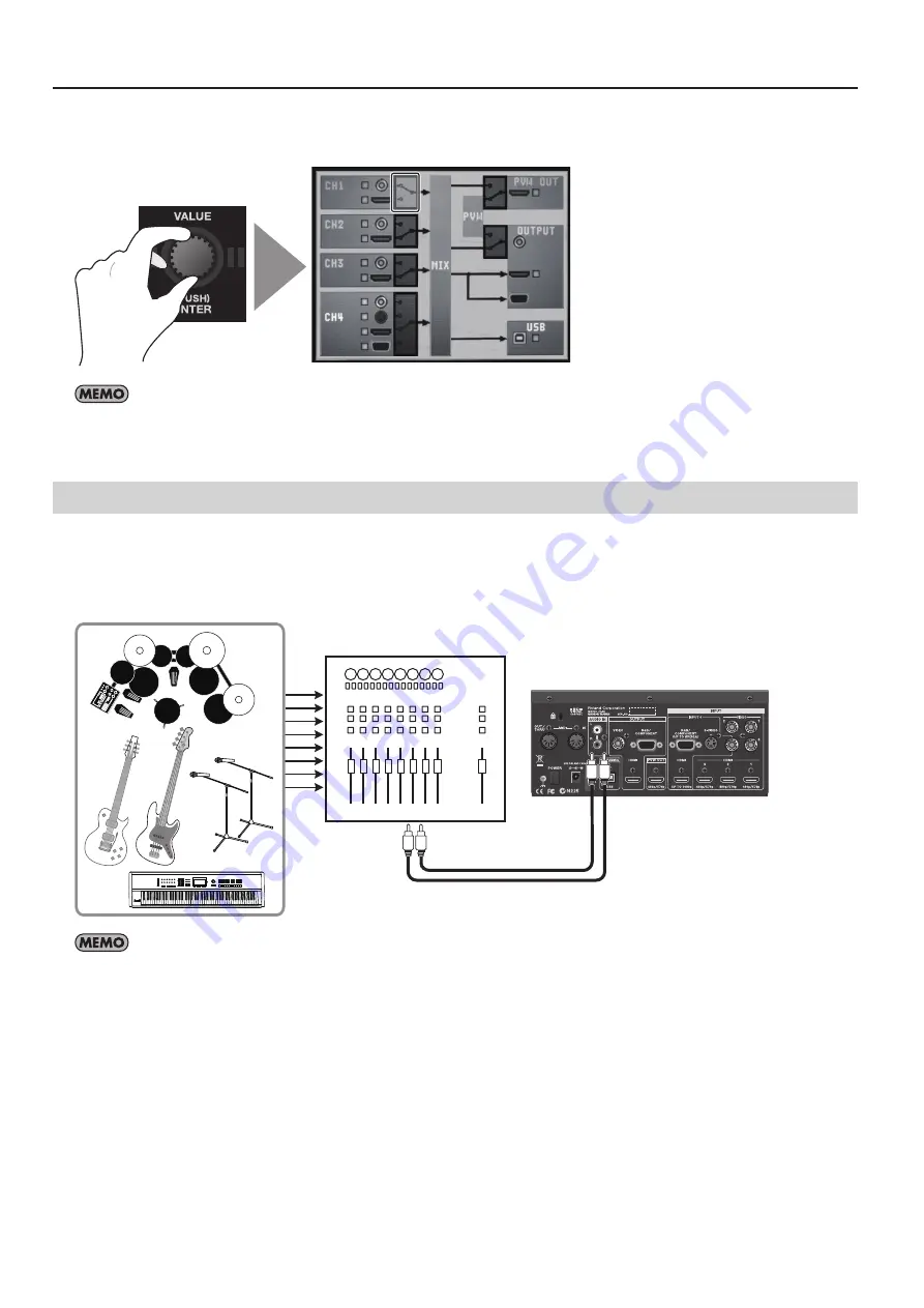
Connecting Audio Source Equipment

Connect an audio mixer or other source device to the AUDIO IN connectors. Input made via these connectors is output from the 
HDMI connectors and the USB port together with the results of video mixing (embedded audio).

*  When connection cables with resistors are used, the volume level of equipment connected to the inputs (AUDIO IN) may be low. If this happens, 

use connection cables that do not contain resistors.

fig.audio-connection.eps

Audio Mixer

Use the menus to adjust the balance/volume of the audio output (p. 36) or delay its timing to sync with the video (p. 37).

Содержание V-4EX

Страница 1: ... mentioned in this document are trademarks or registered trademarks of their respective owners Before using this unit carefully read the sections entitled USING THE UNIT SAFELY p 3 and IMPORTANT NOTES p 5 These sections provide important information concerning the proper operation of the unit Additionally in order to feel assured that you have gained a good grasp of every feature of your new unit ...

Страница 2: ...2 ...

Страница 3: ...ct sunlight in an enclosed vehicle near a heating duct on top of heat generating equipment or are Damp e g baths washrooms on wet floors or are Exposed to steam or smoke or are Subject to salt exposure or are Humid or are Exposed to rain or are Dusty or sandy or are Subject to high levels of vibration and shakiness WARNING 007 Do not place in an unstable location Make sure you always have the unit...

Страница 4: ...terfere with their proper ventilation 102c When disconnecting an AC adaptor grasp it by the plug To prevent conductor damage always grasp the AC adaptor by its plug when disconnecting it from this unit or from a power outlet CAUTION 103b Periodically clean the AC adaptor s plug At regular intervals you should unplug the AC adaptor and clean it by using a dry cloth to wipe all dust and other accumu...

Страница 5: ... avoid the loss of data However in certain cases such as when circuitry related to memory itself is out of order we regret that it may not be possible to restore the data and Roland assumes no liability concerning such loss of data Additional Precautions 551 Please be aware that the contents of memory can be irretrievably lost as a result of a malfunction or the improper operation of the unit To p...

Страница 6: ...ord fig PSB1U eps RCA BNC conversion plug two fig RCA BNC plug eps Owner s manual fig owners manual eps The explanations in this manual include illustrations that depict what should typically be shown by the display Note however that your unit may incorporate a newer enhanced version of the system e g includes newer sounds so what you actually see in the display may not always match what appears i...

Страница 7: ...ing a Preview Monitor 19 Connecting a Computer for Streaming 20 Checking the Connections 22 About Input Output Formats 23 Inputting HDCP Signals 24 Basic Operations 25 Switching the Monitor View Mode 25 Changing Various Settings 26 Switching the Video 27 Switching the Picture Using the Video Fader 27 Switching Using the Touch Panel 28 Switching Using the Transformer Buttons 29 Switching Automatica...

Страница 8: ...ettings 37 Making the Settings for Video Fader Operation 38 Menu Operations and Menu List 39 Menu Operations 39 Menu List 40 Appendices 44 Main Specifications 44 Effects List 45 Calibrating and Changing the Installed Orientation of the Video Fader 56 About Remote Control 58 Security Slot 58 Dimensions 58 Troubleshooting 59 Index 60 ...

Страница 9: ...ular setup you may experience a discomforting sensation or perceive that the surface feels gritty to the touch when you touch this device or the metal portions of a video camera monitor or other devices connected to it This is due to an infinitesimal electrical charge which is absolutely harmless However if you are concerned about this connect the ground terminal see figure to an external ground W...

Страница 10: ...rning the Power Off Press the POWER button on the rear panel The buttons and indicators on the top panel go dark and the power to the V 4EX is switched off About AUTO OFF When all of the conditions described below continue for 240 minutes or longer the V 4EX automatically powers down AUTO OFF feature No operation of the unit including operation by remote control No video input To keep the power fr...

Страница 11: ...annot be used for switching while the menu screen is displayed Exit the menu when you switch using the touch panel 2 HDCP Indicator This operates as described below depending on the HDCP setting p 24 Lighted It lights up when an HDCP compatible device is connected as the output device Flashing It flashes when no output device is connected or when the connected device is not compatible with HDCP Un...

Страница 12: ...urning counterclockwise applies a fade out to black and turning clockwise applies a fade out to white To apply a fade in return the dial to its center position p 31 The indicator flashes when the dial is at any position other than center 13 FREEZE Button This freezes the final output It lights up while the still video is being output Pressing the control a second time makes it go dark and ends the...

Страница 13: ...es the video between A bus and B bus Adjustment of the amount of keying When you are carrying out chroma or luminance key composition this adjusts the degree of extraction Inset screen display level adjustment When you are carrying out Picture in Picture composition this adjusts the display level of the inset screen By default the video fader is installed vertically operating front to back but you...

Страница 14: ... are each provided with the connectors below Use the menus to select the enabled input connector INPUT 1 3 Connect composite VIDEO or HDMI sources By default HDMI input is enabled for each channel INPUT 4 In addition to composite or HDMI you can also connect sources with S Video or analog RGB 15 pin mini D Sub type outputs By default HDMI input is enabled 5 POWER Button This turns the power to the...

Страница 15: ...nformation on signal formats that can be input and output refer to About Input Output Formats p 23 Signal Flow The internal signal flow of the V 4EX is as shown below fig signal flow eps 1 2 3 4 Frame Sync 480p 576p Input Selector HDMI Video 1 2 3 4 Composite OUT HDMI Video HDMI Video HDMI RGB Component Video RGB Component OUT HDMI OUT Audio In S Video Video Mixer PinP Key Effect A BUS B BUS Audio...

Страница 16: ...s capable of composite output to the VIDEO connectors at INPUT 1 through 4 When connecting equipment that has RCA pin type output connectors use the included RCA BNC conversion plug fig composite connection eps To connect composite source equipment the enabled connector must be switched from HDMI to VIDEO Refer to the following Switching the Enabled Connector and change the setting Making S Video ...

Страница 17: ...ded with component output make the connection using a conversion cable from component to mini D Sub 15 pin type connectors Switching the Enabled Connector Use the procedure described below to enable connectors other than HDMI 1 Display the input setup screen Press the VIDEO button in INPUT section to display the input setup screen for video fig input video button eps 2 Select the channel Use the t...

Страница 18: ...his sequence of composite S Video HDMI RGB component Connecting Audio Source Equipment Connect an audio mixer or other source device to the AUDIO IN connectors Input made via these connectors is output from the HDMI connectors and the USB port together with the results of video mixing embedded audio When connection cables with resistors are used the volume level of equipment connected to the input...

Страница 19: ... of the VC 30HD you can connect a digital video recorder Blu ray Disc recorder or other such device When HDCP is turned on composite and RGB component output is stopped Note however that HDMI output continues p 24 Connecting a Preview Monitor Connect a preview monitor to the PVW OUT connector Output from this connector is 480 59 94p when set to NTSC or 576 50p when set to PAL Connect a compatible ...

Страница 20: ...Edition Professional Edition Service Pack 3 or later Windows Vista Service Pack 2 or later Windows 7 Mac OS X 10 6 or later Connection and operation of the V 4EX with standard computers running the operating systems described above have been verified but connection and operation with all computers satisfying such conditions is not assured Connection or operation may be impossible due to difference...

Страница 21: ...special driver is not necessary The computer recognizes the V 4EX as a USB video class device audio class device Performing Output to a Computer For the video and audio signals from the V 4EX to be viewed and heard correctly on the computer software that supports USB video class and USB audio class must be installed and set up on the computer 1 Prepare output of video or audio Operate the V 4EX to...

Страница 22: ... Pressing the VIDEO button in INPUT section displays the screen shown below A yellow box next to the icon for a connector indicates that the connection is recognized by the V 4EX If the box is gray no connection is detected The recognition status grey or yellow of CH4 s RGB Component connector is displayed only while the connector is selected When it is not selected the display is grey regardless ...

Страница 23: ...t to NTSC 1080 50p when set to PAL S Video Connector INPUT 4 480 59 94i when set to NTSC 576 50i when set to PAL RGB COMPONENT Connector INPUT 4 640 x 480 60 Hz 800 x 600 60 Hz 1024 x 768 60 Hz 1280 x 768 60 Hz 1280 x 1024 60 Hz 1366 x 768 60 Hz 1400 x 1050 60 Hz 1600 x 1200 60 Hz 1920 x 1200 60 Hz The refresh rates noted above are the maximum values for the respective resolutions Output Formats T...

Страница 24: ...n the VALUE dial to change the setting from OFF to ON When the confirmation screen appears press the VALUE dial or use the touch panel to confirm the change fig HDCP setting eps 3 Exit the menu Press the MENU button several times to quit the menu When the setting change just described has been made video output from the composite connector the RGB COMPONENT connector and the USB port is stopped No...

Страница 25: ...r View Mode The V 4EX s built in monitor has the following three types of view modes Use the MONITOR buttons to change the mode OUTPUT This displays the current video output from the V 4EX on a single screen INPUT This displays video input from source equipment on a four way split screen INPUT OUTPUT This displays the current video output by overlaying it on a four way split screen displaying the ...

Страница 26: ...touch panel to choose the transition effect 1 through 3 whose settings you want to change and turn the VALUE dial to select the transition effects assigned to the respective buttons 2 Filter Compositing Effect Pressing the EFFECTS button displays only this area The left side corresponds to Effect buttons 1 through 4 for A Bus and the right side corresponds to Effect buttons 1 through 4 for B Bus U...

Страница 27: ...positing effect red borders are displayed around both pictures 2 Select a transition effect Use the transition effect buttons to select the transition effect you want to apply By default you can select from below 1 MIX The pictures on A and B change gradually 2 WIPE The pictures on A and B change using a wipe 3 EFX The pictures on A and B change using a soft wipe fig transition select eps MIX A A ...

Страница 28: ...the way to the A Bus end or the B Bus end fig select bus eps 3 Use the touch panel to make the switch Touch the monitor to select the output picture When you do this a red border appears around the picture being output The input selector for the bus you selected in step 2 also lights up fig touch select eps Note the following points when you switch video using the touch panel Move the video fader ...

Страница 29: ... make it light up causes automatic switching between A and B Press the BPM SYNC button again and make it go dark to stop the automatic switching fig BMP SYNC button eps Use this feature when you want to perform switching on the rhythm of background music By default switching is performed at 120 BPM beats per minute You can use either of the following two methods to change the BPM setting Setting t...

Страница 30: ... by selecting the area where DIR or TRANS is displayed and turning the VALUE dial DIR This means direct The picture is switched using a cut TRANS This is the default setting and means transition The picture is switched with the currently selected transition effect applied You can select the speed of automatic switching by selecting the area where numeric like x1 4 or x1 2 is displayed and turning ...

Страница 31: ...ight up continuously and returns the unit to 100 output fig fade dial eps About the Output Fade Modes You can select a mode from below by selecting the OUT FADE area of BPM setting screen and turning the VALUE dial Manual This is the default setting Apply a white or black fade by turning the dial Auto A fade in fade out is repeated automatically The speed varies according to the position of the di...

Страница 32: ...ter effect eps 3 Adjust the amount of effect Turn the A Bus Effect Control dial to adjust the amount of effect fig A bus control dial eps The default filter effects change as follows when you turn the Effect Control dial FEEDBACK Turning the control clockwise shortens the repeating interval NEGATIVE Turning the dial clockwise cycles through these settings brightness inversion color inversion brigh...

Страница 33: ... with the background picture as an inset screen fig composition effects eps Key Compositing You can use the KEY menu p 40 to change settings like the extraction color for chroma key or luminance key Compositing Using Chroma Key Using chroma key you can composite video that has a blue or green background Blue is extracted by default fig chroma key image eps Chroma Key Blue Green 1 Choose the backgr...

Страница 34: ...image eps Luminance Key Black White 1 Choose the background picture Use the A Bus input selectors to select the channel of the background 2 Select the video to display in the foreground Use the B Bus input selectors to select the channel to be displayed in the foreground To composite a logo or text input from a computer select 4 Enable the input connector where the computer is connected 3 Perform ...

Страница 35: ...ress the OUTPUT MONITOR button to display the composited results on the built in monitor You can change the position of the inset screen by sliding your finger on the touch panel fig adjust inset position eps 6 Adjust the display level of the inset screen You can adjust the display level of the inset screen by moving the video fader forward or backward Moving it all the way to the B Bus end displa...

Страница 36: ...r each channel Use the touch panel to select from among CH 1 to CH 4 or IN then turn the VALUE dial to raise or lower the level CH 1 through CH 4 correspond to HDMI inputs 1 through 4 IN corresponds to analog input fig adjust ch level eps 3 Adjust the volume of the final output Use the touch panel to select MIX then turn the VALUE dial to raise or lower the level fig adjust out level eps 4 Close t...

Страница 37: ...n a range of 0 0 to 4 0 frames and D2 in a range of 0 0 to 2 0 frames fig adjust delay eps 3 Close the setup screen Press the AUDIO button in the INPUT section to return to the original screen Saving Settings The MEMORY dial on the V 4EX has positions from 1 to 8 You can save the button and dial settings described below to 2 through 7 Effects assigned to A Bus and B Bus Effect buttons Settings of ...

Страница 38: ...or protection Making the Settings for Video Fader Operation Operation Mode of the Video Fader When video is switched using the Transformers or BPM SYNC situations might occur in which the position of the video fader does not match the actual output Selecting QUICK as the operation mode lets you make the actual output match the position of the video fader instantly when you move the fader Note howe...

Страница 39: ...ayed If you do not find the item you want to set on the first page you can use the left and right cursor buttons or the VALUE dial to scroll the displayed pages 3 Select a parameter Select a parameter by turning and pressing the VALUE dial or by using the touch panel on the built in monitor If the parameter cannot be displayed on just one page you can use the VALUE dial or the up and down buttons ...

Страница 40: ...tions 1 through 8 of the video fader Making this setting lets you use multiple transition effects in combination USER 1 4 POSITION 1 001 227 this specifies the effect assigned to position 1 A Bus end POSITION 2 This specifies the effect assigned to position 2 POSITION 3 This specifies the effect assigned to position 3 POSITION 4 This specifies the effect assigned to position 4 POSITION 5 This spec...

Страница 41: ...po PinP Menu Use the PinP 1 4 button or PinP 5 8 button to access the setup menu Select a value from 1 to 8 then make the settings for the following items PinP 1 8 correspond to effect numbers 142 150 You can access the settings for PinP 1 8 by pressing the EFFECTS button SAVE CURRENT PinP This saves the current PinP settings H POSITION 0 705 This specifies the position of the inset screen in the ...

Страница 42: ...s between scanning lines COLOR 0 64 127 This adjusts the color INPUT RESOLUTION AUTO 480 576i 480 576p 720p 1080i 1080p 640x480 800x600 1024x768 1280x768 1280x1024 1366x768 1400x1050 1600x1200 1920x1200 This sets the input resolution This setting is effective when the input setting for channel 4 is HDMI or RGB COMPONENT The valid setting range of H POSITION and V POSITION differs depending of the ...

Страница 43: ...ring NAM FAM transition p 45 FADER MODE NORMAL QUICK This selects the operation mode of the video fader FADER CURVE CURVE A CURVE B CURVE C This selects the operating curve of the video fader FADER CALIBRATE A This performs calibration of the video fader at the A Bus end FADER CALIBRATE B This performs calibration of the video fader at the B Bus end LCD PREVIEW ASPECT 16 9 4 3 This selects the asp...

Страница 44: ...Impedance RGB Component Signal Level 1 0 Vp p luminance 0 7 Vp p chroma Impedance 75 ohms Composite Signal Level 1 0 Vp p Impedance 75 ohms S Video Signal Level 1 0 Vp p Impedance 75 ohms Analog Audio Nominal Input Level 10 dBu Maximum Input Level 8 dBu Impedance 15 k ohms Video Effects Transition Mix Cut Wipe 259 patterns Composition Filter Picture in Picture Luminance Key Chroma Key Strobe Negat...

Страница 45: ... no effect indicated by an is assigned to the button the button lights up steadily when pressed In such cases operation of the Effect Control dial has no effect Transition Effects Mix fig MIX eps 001 Mix01 The A and B video is switched gradually 002 Fam01 This is an abbreviation of full additive mix The A and B luminance levels are maintained during the transition 003 Fam You can move the A B cros...

Страница 46: ...es Wipe m In the following wipe illustrations black areas represent the picture after the transition the picture that appears and white areas represent the picture before the transition the picture that disappears ...

Страница 47: ...47 Appendices ...

Страница 48: ...48 Appendices ...

Страница 49: ...49 Appendices ...

Страница 50: ...us picture 205 Key02 The light part of the A Bus picture transitions to the dark part of the B Bus picture 206 Key03 The light part of the B Bus picture transitions to the dark part of the A Bus picture 207 Key04 The dark part of the B Bus picture transitions to the light part of the A Bus picture fig key icons eps 204 Key01 205 Key02 206 Key03 207 Key04 ...

Страница 51: ...51 Appendices Slide Normal Slide Sequential ...

Страница 52: ...52 Appendices Stretch ...

Страница 53: ...OR8 067 MONOCOLOR 068 EMBOSS1 Emboss concave convex image 075 EMBOSS8 076 EMBOSS 082 COLORPASS1 Color pass making monochrome while leaving a specific color 089 COLORPASS8 090 COLORPASS 091 W LUMIKEY Luminance key white extraction 092 W LUMIKEY 093 B LUMIKEY Luminance key black extraction 094 B LUMIKEY No Effect name Description 095 CHROMAKEY Chroma key 096 CHROMAKEY 097 FLIP H Flip left right flip...

Страница 54: ...ges the color of the color filter 076 EMBOSS Smoothly changes the color applied to the image 081 POSTERIZE Change the strength of the effect four levels 090 COLORPASS Change the color that remains eight types 092 W LUMIKEY Change the white luminance level 094 B LUMIKEY Change the black luminance level 096 CHROMAKEY Change the chromakey level 100 FLIP Change the direction in which the image is flip...

Страница 55: ...MONOCOLOR EMBOSS POSTERIZE COLORPASS COLORIZE NEGATIVE COLORIZE FINDEDGE SILHOUETTE MONOCOLOR EMBOSS POSTERIZE COLORPASS FINDEDGE NEGATIVE COLORIZE FINDEDGE SILHOUETTE MONOCOLOR EMBOSS POSTERIZE COLORPASS SILHOUETTE AFTERIMAGE FEEDBACK NEGATIVE COLORIZE FINDEDGE SILHOUETTE MONOCOLOR EMBOSS POSTERIZE COLORPASS W LUMIKEY B LUMIKEY CHROMAKEY PinP MONOCOLOR NEGATIVE COLORIZE FINDEDGE SILHOUETTE MONOCO...

Страница 56: ...ton to access the menu screen then use the touch panel to select SETUP fig utility menu eps 3 Calibrate the A Bus position Select Video Fader Calibrate A and press the VALUE dial The display changes to a confirmation screen Press the VALUE dial once more fig calibrate menu eps 4 Move to the B Bus end Move the video fader all the way to the B Bus position 5 Calibrate the B Bus position Select Video...

Страница 57: ... 3 Change the orientation of the video fader Rotate the video fader 90 degrees When doing this align the triangular symbol printed on the video fader panel circular with the triangular symbol printed on the V 4EX s top panel fig turn fader eps Align the triangular symbols When changing the orientation of the video fader never pull the video fader upward or rotate it more than 90 degrees Doing so m...

Страница 58: ... www rolandsystemsgroup net MIDI VISUAL CONTROL The V 4EX can be operated remotely from a device that supports MIDI Visual Control MIDI Visual Control is a feature that uses MIDI to link visual expression to a musical performance fig MVC logo eps Security Slot You can attach a commercially available security wire here to prevent theft http www kensington com fig kensington eps Dimensions fig dimen...

Страница 59: ...PAL Connect equipment that supports these output formats Nothing is displayed on the built in monitor Is any of the MONITOR buttons illuminated Nothing is displayed when all are dark Video cannot be switched using the touch panel Has the video fader been moved all the way to one end of its stroke The touch panel cannot be used to perform a transition when the video fader has not been moved all the...

Страница 60: ...e 31 H HDCP 24 HDMI 16 L Lip sync 37 Luminance Key 34 M MEMORY 37 Menu 39 MIDI 58 MIDI VISUAL CONTROL 58 Monitor 11 O Operating System 20 Orientation 57 P Picture in Picture 35 Preview Monitor 19 Projector 19 R Remote Control 58 RGB 17 S Signal Flow 15 Source 16 Streaming 20 S Video 16 Switching 27 T Touch Panel 28 transition effect 27 Transition Section 13 U User Transition 41 V Video Fader 27 Vi...

Страница 61: ...61 Model Name Type of Equipment Responsible Party Address Telephone V 4EX Video Mixer Roland Systems Group U S 5100 S Eastern Avenue Los Angeles CA 90040 2938 U S A 323 890 3700 ...

Страница 62: ...62 ...

Страница 63: ...63 ...

Страница 64: ......

Отзывы: