background image


122


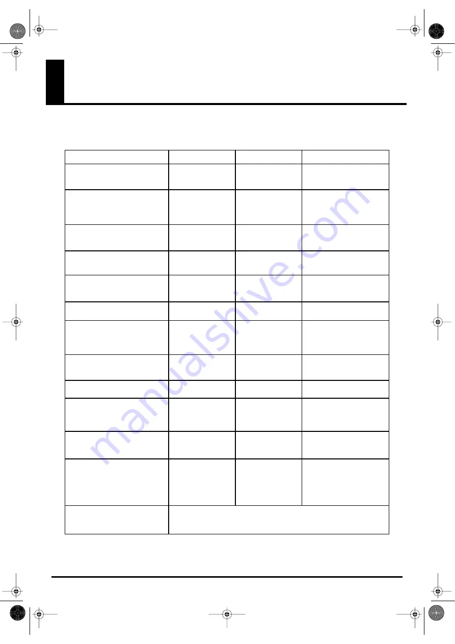
MIDI Implementation Chart

X

1–16

Select patches

Control various parameters

Control various parameters

Select patches

Switch banks (0

–7)

Control various parameters

Control various parameters

X
X

X
X

**************   

X
O

O
O
O

O

O

1–16

O

X

1–16

X
X

**************

X
X

0–127
    

X
O

O

O
O
O

O

1–16

*1 Only when the note mode is Assignable (this can be set)
*2 Switchable between 

OX

.

Visual Synthesizer

Model CG-8 

Date : May 1, 2005

Version : 1.00

**************

**************

**************

*1

*1

*2

*2

*2

*2
*2

*2
*2

*2

MIDI Implementation Chart

Basic
Channel

Default
Changed

Mode

Default
Messages
Altered

Note
Number :

True Voice

Velocity

Note On
Note Off

After
Touch

Key’s
Channel’s

Pitch Bend

0, 32
1

31

33

120

Control
Change

Program
Change

True Number

System Exclusive

System
Common

: Song Position
: Song Select
: Tune Request

System
Real Time

: Clock
: Commands

Aux
Messages

: All Sound Off
: Reset All Controllers
: All Notes Off
: Active Sensing
: System Reset

Notes

Function...

Transmitted

Recognized

Remarks

Stored after power down

O : Yes
X : No

X
X
X

X
X

X
X
X
X
X

O

X
X
X

X
X

X
X
X
X
X

CG8_e.book 122 ページ 2005年4月20日 水曜日 午後12時3分

Содержание CG-8

Страница 1: ...See the sound Hear the visuals CG 8_Cover fm 1 ページ 2005年4月20日 水曜日 午前9時51分 ...

Страница 2: ...CG 8_Cover fm 2 ページ 2005年4月20日 水曜日 午前9時51分 ...

Страница 3: ...Additionally in order to feel assured that you have gained a good grasp of every feature provided by your new unit OWNER S MANUAL should be read in its entirety The manual should be saved and kept on hand as a convenient reference 202 Copyright 2005 ROLAND CORPORATION All rights reserved No part of this publication may be reproduced in any form without the written permission of ROLAND CORPORATION ...

Страница 4: ...d grounding prong The wide blade or the third prong are provided for your safety If the provided plug does not fit into your outlet consult an electrician for replacement of the obsolete outlet WARNING IMPORTANT As the colours of the wires in the mains lead of this apparatus may not correspond with the coloured markings identifying the terminals in your plug proceed as follows The wire which is co...

Страница 5: ...kind water soft drinks etc to penetrate the unit 012a Immediately turn the power off remove the power cord from the outlet and request servicing by your retailer the nearest Roland Service Center or an autho rized Roland distributor as listed on the Information page when The power supply cord or the plug has been damaged or If smoke or unusual odor occurs Objects have fallen into or liquid has bee...

Страница 6: ...ed so that its location or position does not interfere with its proper venti lation 102b Always grasp only the plug on the power supply cord when plugging into or unplugging from an outlet or this unit 103a At regular intervals you should unplug the power plug and clean it by using a dry cloth to wipe all dust and other accumulations away from its prongs Also disconnect the power plug from the pow...

Страница 7: ...t dry cloth 402 Never use benzine thinners alcohol or solvents of any kind to avoid the possibility of discoloration and or defor mation Repairs and Data 452 Please be aware that all data contained in the unit s memory may be lost when the unit is sent for repairs Important data should always be backed up on a memory card or written down on paper when possible During repairs due care is taken to a...

Страница 8: ...ding monetary compensation for the loss of any recorded content in the event of the malfunction of or physical damage to the hard disk or for any direct or incidental damages resulting from the loss of such data Precautions Regarding Setup and Use 812 Certain hard disk setup procedures and usage conditions may result in the corruption of recorded data malfunc tioning or physical damage to the disk...

Страница 9: ... to the data included in this product is the property of the respective copyright holder s For details refer to the included License agreement 982 The demo data of this unit is not transmitted from the MIDI OUT connector 985 The explanations in this manual include illustrations that depict what should typically be shown by the display Note however that your unit may incorporate a newer enhanced ve...

Страница 10: ...d 27 Images 27 Projects 28 Patches Effects and Pictures 29 Selecting a project 31 Selecting a Photo Patch and playing back the image 32 Selecting a Photo Patch 32 Selecting a Stamp Patch to layer on the image 33 Selecting a Stamp Patch 33 Applying an effect to the image 34 Various playback methods 36 Using the XY pad to apply effects to the image 36 Using the D Beam to apply effects to the image 3...

Страница 11: ... Editing the parameters of a Stamp Effect 76 Applying modulation to the parameters of a Stamp Effect 77 Making XY pad D Beam and Foot Pedal settings 79 Saving a Stamp Patch the Save operation 83 Managing projects and pictures 84 Folder and file related operations 84 Copying 85 Deleting 89 Renaming 91 Creating a folder 94 Formatting a CompactFlash card 97 Caution when formatting 97 Formatting proce...

Страница 12: ... wide range of expressive transformations can be created by applying effects to the images you load Combine two image layers You can combine two layers background and foreground for example by adding a logo or other foreground to a background image to project your message effectively Use music to control images The CG 8 can analyze sound from its LINE IN jacks or internal mic and apply a visual ef...

Страница 13: ...s playback methods p 36 This explains the various ways in which you can play back images using the CG 8 Learning more about the CG 8 p 45 This explains concepts and terms you ll need to know when using the CG 8 and describes the operating screens and basic structure of the CG 8 About projects p 50 This explains project related operations such as how to load images into the CG 8 Creating patches p ...

Страница 14: ...pplied p 38 5 REC button This button records movements of the parameter knobs XY pad and D Beam for ten seconds Recording will begin when you press the button lit red p 39 6 GRAB MOTION switch This plays back the parameter knob XY pad and D Beam movements you recorded using the REC button LOOP The recorded movement will play repeatedly OFF The patch will play normally 1 SHOT The recorded movement ...

Страница 15: ...y the Sound Control function is detected p 43 14 SHUTDOWN button When the power is on you can press and hold this button for two seconds to put the CG 8 in standby mode In standby mode press this button to turn the CG 8 on The illumination of the button indicates the unit s status as follows Lit blue On Lit red Standby Unlit Off p 26 15 HDD indicator This will light when the CG 8 is accessing its ...

Страница 16: ...ty of effects to the image p 36 p 68 p 79 32 RATE knob This adjusts the speed of modulation for the effect p 34 p 66 p 77 33 DEPTH button Press this the button will light and you can use the COLOR SPEED X Y Z knobs to adjust the depth of modulation p 34 p 66 p 77 34 MODULATION knob This selects the type of effect modulation If you choose SOUND 1 SOUND 2 or SOUND 3 the external audio input will mod...

Страница 17: ...television or other device used for monitoring p 22 5 OUTPUT S VIDEO connector This connector transmits an S video signal You can connect it to your television or other device used for monitoring p 22 6 OPTION connector Connect the included card adaptor here p 18 7 OUTPUT RGB connector Connect a display here Use a display that provides an analog RGB D sub 15 pin connection at VGA 640 x 480 resolut...

Страница 18: ... on the CompactFlash card Don t connect more than one card adaptor simultaneously CompactFlash cards are not included with the CG 8 You will need to obtain them separately Make sure that the CG 8 s power is switched off then connect the card adaptor to the rear panel OPTION connector as shown below fig Card02 e EPS About the card adaptor Connecting the card adaptor Card adaptor 930 Don t connect o...

Страница 19: ...hould go in first and the side that should face upward then push the CompactFlash card into the slot as far as it will go Do not use excessive force Insert the CompactFlash card into the card adaptor as shown below fig Card04 EPS Removing a CompactFlash card When you insert a CompactFlash card the button located beside the card slot will pop out When you press this button the inserted CompactFlash...

Страница 20: ...on the card Be sure to double check before you format a card Formatting procedure Cards are formatted in the FILE MANAGER screen For details refer to Formatting a CompactFlash card p 97 When inserting Carefully note the end that should go in first and the side that should face upward then push the CompactFlash card into the slot as far as it will go Do not use excessive force When removing Grasp t...

Страница 21: ...linked with certain expressive elements of a musical performance For example a V LINK compatible MIDI device can be used to control the CG 8 fig vlink con1 e For details on using V LINK refer to Using V LINK p 101 What is V LINK Remote functions V LINK Video output V Synth MIDI cable CG 8 Display or projector CG8_e book 21 ページ 2005年4月20日 水曜日 午後12時3分 ...

Страница 22: ...mize the volume of all devices and turn off the power before connecting other devices 926a The volume from the device connected to the LINE IN jacks may be diminished if you use a cable with a built in resistor to make connections If so use a connection cable that does not contain a resistor e g the Roland PCS series of cables fig connect e eps For details on the card adaptor refer to About the ca...

Страница 23: ... fig connect v link e EPS If you re controlling the CG 8 from the MC 909 make connections as follows fig connect MC909 e EPS Example setups VJ performance V Synth CD player etc MIDI cable Audio cable VGA cable Video cable S video cable etc CG 8 Display or projector MC 909 CG 8 CD player etc MIDI cable Audio cable VGA cable Video cable S video cable etc Display or projector CG8_e book 23 ページ 2005年4...

Страница 24: ...quencer software running on your computer make connections as follows fig connect CPU e EPS Using a sequencer to control the CG 8 CG 8 Computer MIDI interface e g UM 550 USB cable MIDI cable VGA cable Video cable S video cable etc Display or projector CG8_e book 24 ページ 2005年4月20日 水曜日 午後12時3分 ...

Страница 25: ...be used as video sources and received by a video device such as the DV 7DL fig connect DV e EPS Using images played by the CG 8 as video sources Video cable S video cable etc VGA cable DV 7DL CG 8 Scan rate converter Video cable Display or projector CG8_e book 25 ページ 2005年4月20日 水曜日 午後12時3分 ...

Страница 26: ... display panel will indicate Load When the CG 8 has started up the display panel will indicate 1 Press and hold the SHUTDOWN button for two seconds or longer The SHUTDOWN button will blink red blue shutdown in progress After a time the SHUTDOWN button will light red standby mode 2 Press the POWER switch located on the CG 8 s rear panel The SHUTDOWN button s light goes out 945 If you need to turn o...

Страница 27: ...nd Stamp Patches each consist of a picture image and an effect for the photo or stamp fig photo stamp02 e EPS In addition each effect can apply change or movement to the picture You can also create a variety of visual effects by controlling the location and movement parameters You can also use controllers such as the XY pad and D Beam to control the image in real time How the CG 8 is organized Ima...

Страница 28: ...ber of patches fig structure04 e EPS Projects Project Photo Picture Assign the desired Stamp Picture Stamp Picture Assign the desired Photo Picture Photo Patch Stamp Patch Photo Picture Stamp Picture Photo Effect Stamp Effect Select and play back the desired Photo Patch Select and play back the desired Stamp Patch For more about projects refer to About projects p 50 CG8_e book 28 ページ 2005年4月20日 水曜...

Страница 29: ... These are respectively called Photo Effects and Stamp Effects and are managed by their bank and number in the same way as patches You can switch effects by using Visual Pads 1 16 fig effect e eps Photo Effects p 63 Stamp Effects p 74 Patches Effects and Pictures Photo Patches Bank 1 Bank 8 Bank 1 Bank 8 Stamp Patches For details on creating and saving Photo Patches and Stamp Patches refer to Crea...

Страница 30: ...managed by bank and number in the same way as the patches and effects described earlier fig picture e eps A single project can use up to 48 Photo Pictures 16 x 3 banks and up to 16 Stamp Pictures Photo Pictures p 64 Stamp Pictures p 75 For more details about how the CG 8 is organized refer to Learning more about the CG 8 p 45 For details on how to load a picture into a project and assign it to a v...

Страница 31: ...l will blink 2 To select a project press a visual pad 1 16 that is lit The visual pad you pressed and the CHANGE PROJECT button will blink In the right side of the display panel the number of the visual pad you pressed will blink 3 Press the CHANGE PROJECT button The button will go out and the CG 8 will begin loading the selected project The display panel will indicate Load When the selected proje...

Страница 32: ...ad 1 8 While you continue holding down the PHOTO PATCH pad the visual pad of the currently selected bank number will blink 2 When you take your finger off the PHOTO PATCH pad visual pads 1 16 in which a Photo Patch is saved will light 3 Press one of the lit visual pads 1 16 to select a patch The selected Photo Patch will begin playing The display panel will indicate the bank and number of that Pho...

Страница 33: ...s a visual pad 1 8 to switch banks While you continue holding down the STAMP PATCH pad the visual pad of the currently selected bank number will blink 2 When you take your finger off the STAMP PATCH pad visual pads 1 16 in which a Stamp Patch is saved will light 3 Press one of the lit visual pads 1 16 to select a patch The selected Stamp Patch will begin playing The display panel will indicate the...

Страница 34: ... The parameter knobs will adjust the modulation cyclic change of the image First use the MODULATION knob to select the type of modulation e g smooth motion or random motion Then use the parameter knobs to adjust how that motion is to occur The X knob Y knob and Z knob will mainly change the direction of the motion The SPEED knob adjusts the speed of motion and the COLOR knob adjusts the color chan...

Страница 35: ...knob Adjusts the modulation depth for Z axis forward backward modulation such as Z position or rota tional angle MODULATION knob Selects the type of modulation RATE knob Adjusts the speed of modulation COLOR knob Adjusts the depth of color related modulation SPEED knob Adjusts the depth of speed related modulation X knob Adjusts the modulation depth for X axis left right modulation such as X posit...

Страница 36: ...2 Move your finger left right X axis or up down Y axis on the XY pad The effect will be applied fig XY eps When the XY pad is responding the XY PAD ACTIVE indicator will light If you press the HOLD button it will light the effect will be maintained even if you take your finger away from the XY pad Using the XY pad to apply effects to the image For each patch the choice of parameter that will be co...

Страница 37: ... point on the time axis The strobe effect applies to both the Photo Patch and the Stamp Patch 1 Press the STROBE button The button will light If you press the STROBE button when the ASSIGNABLE button is lit i e the Assignable function is on the ASSIGNABLE button will go out and the Assignable function will turn off The Strobe function and Assignable function cannot both be on at the same time 2 Pl...

Страница 38: ... the Assignable function cannot both be on simultaneously 3 Place your hand over the D Beam and slowly move it up and down to apply the effect The left D BEAM indicator will light when the left D Beam sensor is responding the right indicator when the right sensor is responding and both indicators when both sensors are responding 4 Press the ASSIGNABLE button the button will go out and the D Beam w...

Страница 39: ...omatically when ten seconds have elapsed 5 Use the GRAB MOTION switch to play back the recorded motion Recording and reproducing the motion of an image LOOP The recorded motion will play back as a loop OFF The patch will play normally If you move the switch from LOOP or 1 SHOT to OFF the patch will play as it did when you turned it OFF 1 SHOT The recorded motion will play back as long as you hold ...

Страница 40: ... pausing the image the Trigger function RESTART When you move the switch to this position it will be cued to the beginning and playback will start When you release the switch it will automatically return to the OFF position and the patch will play normally OFF The Trigger function will be off and the patch will play nor mally STROBE The Strobe effect will be applied The image will pause when you p...

Страница 41: ...b to specify the center frequency at which you want to detect peaks in the audio Turn the PEAK FREQ toward the left if you want to detect low frequency peaks such as bass drum or toward the right if you want to detect high frequency peaks such as cymbal The DETECTION indicator will light when the CG 8 detects peaks in the region you specify As a special case turning the PEAK FREQ knob all the way ...

Страница 42: ...arameters of a Photo Effect p 66 For details on modulating a Stamp Effect refer to Applying modulation to the parameters of a Stamp Effect p 77 Switching patches at the detected audio peaks If you want patches to switch automatically at the timing of the detected peaks set the AUTO SWITCH to SOUND Independently from the method of control using the peaks detected by the Sound Control function there...

Страница 43: ...ng patches automatically Auto Switch function SPEED Patches will switch at the speed specified by the SPEED knob The patch will switch the instant that the SPEED indi cator located above the knob lights Watch the indicator while you turn the SPEED knob to adjust the speed OFF The Auto Switch function will be off SOUND Patches will switch when external audio peaks are detected as specified by the S...

Страница 44: ...y selected bank will be selected If you want to select patches from another bank use the PHOTO PATCH pad or the STAMP PATCH pad to switch banks Using a foot pedal Using a foot pedal to switch patches Pedal Shift function Foot pedal DP 2 The foot pedal assignment can be saved separately for each patch as part of the patch settings This lets you create patches that contain the most effective setting...

Страница 45: ...Bank 1 Bank 8 Photo Picture 16 pictures x 3 banks Bank 1 Bank 1 Bank 1 Bank 8 Bank 1 Bank 1 Stamp Picture 16 pictures Photo Patches 16 patches x 8 banks Select the photo picture used by each Photo Patch XY pad and D Beam foot pedal settings for each Photo Patch Pictures Pictures taken with a digital camera Pictures created on your computer Select the photo picture used by each Stamp Patch XY pad a...

Страница 46: ...ctFlash card via the included card adaptor The loaded files will be assigned to the visual pads as Stamp Pictures p 57 4 Select the effect you want to use on the Photo Patch background image and adjust the parameters as desired Also at this time select the image you want to use from the Photo Pictures you assigned in step 2 and create and save the Photo Patch p 62 5 Select the effect you want to u...

Страница 47: ...ctures The pictures used by Photo Patches are called Photo Pictures These are JPEG files loaded into the project from the internal hard disk or a CompactFlash card via the included card adaptor To use Photo Pictures you assign them to the visual pads 1 16 Up to 48 Photo Pictures can be assigned to a project Photo Pictures are organized by bank and number within each project and can be recalled usi...

Страница 48: ...PNG files loaded into the project from the internal hard disk or a CompactFlash card via the included card adaptor To use Stamp Pictures you assign them to the visual pads 1 16 Up to 16 Stamp Pictures can be assigned to a project Stamp Pictures are organized by number within each project there are no banks for Stamp Pictures and can be recalled using visual pads 1 16 Refer also to How the CG 8 is ...

Страница 49: ...ITOR screen where you can perform project related operations p 50 FILE MANAGER Enter the FIILE MANAGER screen where you can manage files and format CompactFlash cards p 84 SYSTEM SETTINGS Enter the SYSTEM SETTINGS screen where you can make MIDI related settings p 101 Use the PREV NEXT buttons to select a menu and press the ENTER button to enter that menu screen Play mode Menu mode Main menu screen...

Страница 50: ...een to make settings Project related operations Except for the operation of selecting a project the operations here are performed in Menu mode p 49 using the MENU button EXIT button ENTER button PREV NEXT buttons and VALUE dial fig front15 e eps MENU button In Play mode p 49 press and hold this button two seconds or longer to access the MAIN MENU screen If you press this button in Menu mode the me...

Страница 51: ...the ENTER button The PROJECT EDITOR screen will appear fig project menu01 e eps Creating a new project Don t insert or remove a CompactFlash card while a menu screen is shown i e in Menu mode Doing so may damage the data on the CompactFlash card Guide In the screen project names will be shown in locations corresponding to the visual pads to which a project has already been assigned If no project h...

Страница 52: ... will appear allowing you to select the destination in which the project is to be created 5 Select the destination in which you want to create the new project fig new project01 e eps Enter the folder selected in the list Cancel the operation and return to the PROJECT EDITOR screen Return to the next higher level Make your selection using the PREV NEXT buttons then press the ENTER button to confirm...

Страница 53: ...reen and the project will be assigned to the visual pad you selected in step 4 If in step 3 you selected a project to which a project was already assigned the message Project already exists will appear In this case press the ENTER button to cancel the operation and return to the PROJECT EDITOR screen NEXT button Moves the cursor toward the right PREV button Moves the cursor toward the left VALUE d...

Страница 54: ...in Menu mode p 49 you can press the EXIT button several times to access the MAIN MENU screen fig main menu01 e eps 2 Use the PREV NEXT buttons to select PROJECT EDITOR and press the ENTER button The PROJECT EDITOR screen will appear fig project menu01 e eps Assigning a project to a visual pad Don t insert or remove a CompactFlash card while a menu screen is shown i e in Menu mode Doing so may dama...

Страница 55: ...e your selection using the PREV NEXT buttons then press the ENTER button to confirm your choice Cancel the operation and return to the PROJECT EDITOR screen Enter the folder selected in the list Return to the next higher level Indicates the current level List Turn the VALUE dial to select Folder You can t directly select a project from a CompactFlash card If you want to use a project that s stored...

Страница 56: ...ons to choose OK and press the ENTER button If you decide not to delete the assignment choose CANCEL and press the ENTER button You will return to the project menu The visual pad you selected in step 3 will indicate In the screen project names will be shown in locations corresponding to the visual pads to which a project has already been assigned If no project has been assigned this area will indi...

Страница 57: ... JPEG file jpg Size 3000 x 2000 pixels or smaller Stamp Pictures Format PNG file png Size 3000 x 2000 pixels or smaller 1 Press and hold the MENU button for two seconds or longer to access the MAIN MENU screen fig main menu01 eps Editing a project Images that you can use as a Photo Picture or Stamp Picture Assigning a Photo Picture or Stamp Picture to a visual pad When you load an image into a pro...

Страница 58: ...eps Guide In the screen project names will be shown in locations corresponding to the visual pads to which a project has already been assigned If no project has been assigned this area will indicate To return to the MAIN MENU screen press the EXIT button Alternatively you can press the MENU button to return to Play mode Guide You can t select a project that is not assigned to a visual pad p 54 If ...

Страница 59: ...Photo Picture or Stamp Picture Example the screen for selecting a Photo Picture fig material assign02 e eps PHOTO 1 Photo Picture bank 1 PHOTO 2 Photo Picture bank 2 PHOTO 3 Photo Picture bank 3 STAMP Stamp Picture The locations corresponding to visual pads to which a Photo Picture or Stamp Picture is already assigned will show that image This will be blank if no Photo Picture or Stamp Picture is ...

Страница 60: ... to cancel the operation choose CANCEL 4 A blank space will be created at the location you selected and subsequent pictures will be reordered Be aware that at this time any Photo Picture or Stamp Picture that was assigned to visual pad 16 will be deleted The bank will not change 5 Assign the desired picture as described in step 6 and following of Assigning a Photo Picture or Stamp Picture to a vis...

Страница 61: ...create patches you must first choose the project for which you want to create the patches For details refer to Selecting a project p 31 In order to create a patch you must have loaded the Photo Pictures and Stamp Pictures you want to use into the selected project and assigned them to visual pads 1 16 For details refer to Editing a project p 57 On the CG 8 you will generally create your own patches...

Страница 62: ...TO PATCH pad The PHOTO PATCH pad and any visual pads 1 16 to which Photo Patches are assigned will light 2 Press one of the lit visual pads 1 16 to select a Photo Patch The selected Photo Patch will begin playing The display panel indicates the bank and number of that Photo Patch Creating a Photo Patch Selecting a Photo Patch PHOTO PATCH pad EFFECT pad PICTURE pad Visual pads 1 16 SAVE button PREV...

Страница 63: ...of the lit visual pads 1 16 to select a Photo Effect The Photo Effect will change The display panel indicates the bank and number of that Photo Effect 3 If you want to keep your selection of a Photo Effect perform the Save operation p 72 Selecting a Photo Effect For details on Photo Effects refer to Photo Effects List p 112 While you continue holding down the EFFECT pad the visual pad correspondin...

Страница 64: ...s in the screen This is a convenient way to find the picture you want to use 1 Make sure that the PHOTO PATCH pad is lit and press the PREVIEW button The PREVIEW button will light and the preview screen will appear fig preview photo EPS At the same time the PICTURE pad and visual pads to which a Photo Picture is assigned will light The Photo Pictures in the screen are assigned to the visual pads o...

Страница 65: ...gs you edited perform the Save operation p 72 Editing the parameters of a Photo Effect COLOR knob Adjusts a color related effect SPEED knob Adjusts the speed at which the effect moves FADE knob Adjusts the fade Turn left for fade to black turn right for fade to white X knob Adjusts an X axis left right parameter such as X axis position or rotational angle Y knob Adjusts a Y axis up down parameter ...

Страница 66: ...left will turn modulation off Applying modulation to the parameters of a Photo Effect Modulation will occur in the shape of a sine wave Modulation will occur in the shape of a triangle wave Modulation will occur in the shape of a square wave Modulation will occur in the shape of a sawtooth wave RANDOM Modulation will occur in an irregular shape SOUND1 SOUND2 SOUND3 Modulation will be created by th...

Страница 67: ... on how to adjust the audio input refer to Using an external audio input source to control the image Sound Control function p 41 COLOR knob Adjusts the depth of color related modulation SPEED knob Adjusts the depth of speed related modulation X knob Adjusts the modulation depth for X axis left right parameters such as X axis position or rotational angle Y knob Adjusts the modulation depth for Y ax...

Страница 68: ... eps Making XY pad D Beam and Foot Pedal settings XY pad CONTROLLER ASSIGN button XY PAD ACTIVE indicator D Beam D BEAM indicators For details on using the XY pad refer to Using the XY pad to apply effects to the image p 36 For details on using the D Beam refer to Using the D Beam to apply effects to the image p 37 For details on using the foot pedal refer to Using a foot pedal p 44 For details on...

Страница 69: ...indicate your choice as follows To assign the X axis of the XY pad fig XY X e eps To assign the Y axis of the XY pad fig XY Y e eps To assign the left sensor of the D Beam fig DBEAM L e eps To assign the right sensor of the D Beam fig DBEAM R e eps To assign the foot pedal fig FOOTPEDAL e eps Move your finger along the X axis Move your finger along the Y axis Place your hand above the left sensor ...

Страница 70: ...use the foot pedal to switch patches press any one of the visual pads The CONTROLLER ASSIGN button will blink and the display panel will indicate your choice as follows Example 1 If you selected the X axis of the XY pad in step 2 Control the COLOR knob parameter fig display07 eps Control the SPEED knob parameter fig display08 eps Control the FADE knob parameter fig display09 eps Control the X knob...

Страница 71: ...play28 eps 5 Press the CONTROLLER ASSIGN button The button will go out this completes the assignment The display panel will indicate the currently selected bank and number 6 If you want to save the setting you made perform the Save operation p 72 CG8_e book 71 ページ 2005年4月20日 水曜日 午後12時3分 ...

Страница 72: ...atch number in which you want to save your settings The SAVE button will go out Saving a Photo Patch in another bank 1 While holding down the PHOTO PATCH pad press a visual pad 1 8 to switch banks then release the PHOTO PATCH pad 2 Press the SAVE button The button will light red 3 Press a visual pad 1 16 to specify the Photo Patch number in which you want to save your settings The SAVE button will...

Страница 73: ...P PATCH pad The STAMP PATCH pad and any visual pads 1 16 to which Stamp Patches are assigned will light 2 Press one of the lit visual pads 1 16 to select a Stamp Patch The selected Stamp Patch will begin playing The display panel indicates the bank and number of that Stamp Patch Creating a Stamp Patch Selecting a Stamp Patch Visual pads 1 16 PREVIEW button EFFECT pad PICTURE pad SAVE button STAMP ...

Страница 74: ...f the lit visual pads 1 16 to select a Stamp Effect The Stamp Effect will change The display panel indicates the bank and number of that Stamp Effect 3 If you want to keep your selection of a Stamp Effect perform the Save operation p 83 Selecting a Stamp Effect For details on Stamp Effects refer to Stamp Effects List p 119 While you continue holding down the EFFECT pad the visual pad corresponding...

Страница 75: ...This is a convenient way to find the picture you want to use 1 Make sure that the STAMP PATCH pad is lit and press the PREVIEW button The PREVIEW button will light and the preview screen will appear fig preview stamp EPS At the same time the PICTURE pad and visual pads to which a Stamp Picture is assigned will light The Stamp Pictures in the screen are assigned to the visual pads of the correspond...

Страница 76: ...gs you edited perform the Save operation p 83 Editing the parameters of a Stamp Effect COLOR knob Adjusts a color related effect SPEED knob Adjusts the speed at which the effect moves FADE knob Adjusts the fade Turn left for fade to black turn right for fade to white X knob Adjusts an X axis left right parameter such as X axis position or rotational angle Y knob Adjusts a Y axis up down parameter ...

Страница 77: ...left will turn modulation off Applying modulation to the parameters of a Stamp Effect Modulation will occur in the shape of a sine wave Modulation will occur in the shape of a triangle wave Modulation will occur in the shape of a square wave Modulation will occur in the shape of a sawtooth wave RANDOM Modulation will occur in an irregular shape SOUND1 SOUND2 SOUND3 Modulation will be created by th...

Страница 78: ... on how to adjust the audio input refer to Using an external audio input source to control the image Sound Control function p 41 COLOR knob Adjusts the depth of color related modulation SPEED knob Adjusts the depth of speed related modulation X knob Adjusts the modulation depth for X axis left right parameters such as X axis position or rotational angle Y knob Adjusts the modulation depth for Y ax...

Страница 79: ... eps Making XY pad D Beam and Foot Pedal settings XY pad CONTROLLER ASSIGN button XY PAD ACTIVE indicator D Beam D BEAM indicators For details on using the XY pad refer to Using the XY pad to apply effects to the image p 36 For details on using the D Beam refer to Using the D Beam to apply effects to the image p 37 For details on using the foot pedal refer to Using a foot pedal p 44 For details on...

Страница 80: ...indicate your choice as follows To assign the X axis of the XY pad fig XY X e eps To assign the Y axis of the XY pad fig XY Y e eps To assign the left sensor of the D Beam fig DBEAM L e eps To assign the right sensor of the D Beam fig DBEAM R e eps To assign the foot pedal fig FOOTPEDAL e eps Move your finger along the X axis Move your finger along the Y axis Place your hand above the left sensor ...

Страница 81: ...e the foot pedal to switch patches press any one of the visual pads The CONTROLLER ASSIGN button will blink and the display panel will indicate your choice as follows Example 1 If you selected the left sensor of the D Beam pad in step 2 Control the COLOR knob parameter fig display14 eps Control the SPEED knob parameter fig display15 eps Control the FADE knob parameter fig display16 eps Control the...

Страница 82: ...play28 eps 5 Press the CONTROLLER ASSIGN button The button will go out this completes the assignment The display panel will indicate the currently selected bank and number 6 If you want to save the setting you made perform the Save operation p 83 CG8_e book 82 ページ 2005年4月20日 水曜日 午後12時3分 ...

Страница 83: ...atch number in which you want to save your settings The SAVE button will go out Saving a Stamp Patch in another bank 1 While holding down the STAMP PATCH pad press a visual pad 1 8 to switch banks then release the STAMP PATCH pad 2 Press the SAVE button The button will light red 3 Press a visual pad 1 16 to specify the Stamp Patch number in which you want to save your settings The SAVE button will...

Страница 84: ... file or specify a copy destination fig front15 e eps MENU button In Play mode p 49 press and hold this button for two seconds or longer to access the MAIN MENU screen If you press this button in Menu mode the screen will ask Quit this menu Are you sure Use the PREV NEXT buttons to select OK then press the ENTER button to return to Play mode EXIT button Press this button to return to the previous ...

Страница 85: ...pg PNG files used as Stamp Pictures png Folders Here s how to copy a project picture or folder 1 Press and hold the MENU button for two seconds or longer the MAIN MENU screen will appear If you re in Menu mode p 49 for example when the PROJECT EDITOR screen or the FILE MANAGER screen is displayed press the EXIT button several times to access the MAIN MENU screen fig main menu01 eps Copying Files o...

Страница 86: ...to Play mode Cancel the operation and return to the FILE MANAGER screen Shows information about the project or picture that s selected in the list Turn the VALUE dial to select List Use the PREV NEXT buttons to make your selection then press the ENTER button to confirm your choice Enter the folder you selected in the list Return to the next higher level Indicates the current folder level Files on ...

Страница 87: ...dicates the amount of space remaining on the hard disk or CompactFlash card Cancel the operation and return to the FILE MANAGER screen Use the PREV NEXT buttons to make your selection then press the ENTER button to confirm your choice Enter the folder you selected in the list Return to the next higher level Indicates the current folder level Turn the VALUE dial to select List CG8_e book 87 ページ 200...

Страница 88: ... be executed In this case press the ENTER button to cancel the operation You will return to the FILE MANAGER screen NEXT button Moves the cursor toward the right PREV button Moves the cursor toward the left VALUE dial Selects the character to enter You can use uppercase A Z and lowercase a z letters numerals 0 9 hy phen and _ underline EXIT button Cancels the operation and returns you to the FILE ...

Страница 89: ...to access the MAIN MENU screen fig main menu01 eps 2 Use the PREV NEXT buttons to select FILE MANAGER then press the ENTER button The FILE MANAGER screen will appear fig file manager eps Deleting Don t insert or remove a CompactFlash card while a menu is displayed i e while you re in Menu mode Doing so may damage the data on the CompactFlash card To return to the MAIN MENU screen press the EXIT bu...

Страница 90: ...ER button You will return to the FILE MANAGER screen Shows information about the project or picture that s selected in the list Use the PREV NEXT buttons to make your selection then press the ENTER button to confirm your choice Cancel the operation and return to the FILE MANAGER screen Enter the folder you selected in the list Return to the next higher level Indicates the current folder level Turn...

Страница 91: ...times to access the MAIN MENU screen fig main menu01 eps 2 Use the PREV NEXT buttons to select FILE MANAGER then press the ENTER button The FILE MANAGER screen will appear fig file manager eps Renaming Don t insert or remove a CompactFlash card while a menu is displayed i e while you re in Menu mode Doing so may damage the data on the CompactFlash card To return to the MAIN MENU screen press the E...

Страница 92: ...o the FILE MANAGER screen Use the PREV NEXT buttons to make your selection then press the ENTER button to confirm your choice Enter the folder you selected in the list Return to the next higher level Indicates the current folder level Turn the VALUE dial to select List Files on the CompactFlash card whose filenames include characters that cannot be used by the CG 8 i e characters other than A Z a ...

Страница 93: ...ile already exists will appear and the rename operation cannot be executed In this case press the ENTER button to cancel the operation You will return to the FILE MANAGER screen NEXT button Moves the cursor toward the right PREV button Moves the cursor toward the left VALUE dial Selects the character to enter You can use uppercase A Z and lowercase a z letters numerals 0 9 hyphen and _ underline E...

Страница 94: ...utton several times to access the MAIN MENU screen fig main menu01 eps 2 Use the PREV NEXT buttons to select FILE MANAGER then press the ENTER button The FILE MANAGER screen will appear fig file manager eps Creating a folder Don t insert or remove a CompactFlash card while a menu is displayed i e while you re in Menu mode Doing so may damage the data on the CompactFlash card To return to the MAIN ...

Страница 95: ... folder fig create folder01 e eps Indicates the amount of free space remaining on the hard disk or the CompactFlash card Use the PREV NEXT buttons to make your selection then press the ENTER button to confirm your choice Enter the folder you selected in the list Return to the next higher level Indicates the current folder level Turn the VALUE dial to select List Cancel the operation and return to ...

Страница 96: ... File already exists will appear and the folder cannot be created In this case press the ENTER button to cancel the operation You will return to the FILE MANAGER screen NEXT button Moves the cursor toward the right PREV button Moves the cursor toward the left VALUE dial Selects the character to enter You can use uppercase A Z and lowercase a z letters numerals 0 9 hyphen and _ underline EXIT butto...

Страница 97: ...formatting a card 1 Insert the CompactFlash card that you want to format into the card adaptor included 2 Press and hold the MENU button for two seconds or longer the MAIN MENU screen will appear If you re in Menu mode p 49 for example when the PROJECT EDITOR screen or the FILE MANAGER screen is displayed press the EXIT button several times to access the MAIN MENU screen fig main menu01 eps Format...

Страница 98: ...TER button The display will ask Initialize Memory Card Are you sure 5 Use the PREV NEXT buttons to select OK then press the ENTER button to format the card If you decide not to format select CANCEL and press the ENTER button To return to the MAIN MENU screen press the EXIT button Alternatively you can press the MENU button to return to Play mode Never remove the CompactFlash card while it s being ...

Страница 99: ...tton will light and the Bank area of the display panel will blink fig display20 eps 3 Choose the controller whose sensitivity you want to adjust To choose the XY pad Move your finger on the X axis or X axis of the XY pad To choose the D Beam Place your hand above either the left or right sensor of the D Beam Adjusting the sensitivity of the XY pad and D Beam XY PAD ACTIVE indicator D Beam D BEAM i...

Страница 100: ...u selected the right D Beam sensor fig display24 eps 5 Press the CONTROLLER ASSIGN button to confirm your choice of controller the one for which you are going to adjust the sensitivity 6 Operate the controller you selected in step 3 to specify the upper limit value fig display25 eps 7 Press the CONTROLLER ASSIGN button to confirm the upper limit value 8 Operate the controller to specify the lower ...

Страница 101: ...nobs Modulation type the operation performed by the MODULATION knob Modulation speed the operation performed by the RATE knob Modulation operations performed by the X Y Z COLOR SPEED and FADE knobs The functions that can be controlled will differ depending on your V LINK compatible MIDI device For details on the type of support provided by your MIDI device refer to its owner s manual If you want t...

Страница 102: ...ame Initial Value Keyboard Range Lower 00H Keyboard Range Upper 7FH V LINK Parameter Name Initial Value Color Cb Ctrl Polarity 02H FIXED Output Fade Ctrl Polarity 02H FIXED V LINK Parameter Name CG 8 Parameter Initial Assign Clip Select Patch Number Program Change FIXED Palette Select Patch Bank Number Bank Select FIXED Playback Speed Ctrl Speed Pitch Bend Dual Stream Ctrl Layer Photo Stamp OFF Ti...

Страница 103: ...UT If you re using an external MIDI device to control the CG 8 put the CG 8 in Play mode p 49 When the CG 8 is controlled by MIDI messages it is controlled independently of the current state of its panel operations or operating status The CG 8 can receive System Exclusive messages from another MIDI device In this case you must specify the device ID for the messages you want to receive Set the CG 8...

Страница 104: ...e device ID will appear fig MIDI deviceID eps 4 Turn the VALUE dial to specify the device ID and press the ENTER button The setting will be applied and you will return to the SYSTEM SETTINGS screen If you decide to cancel without setting the device ID use the PREV NEXT buttons to select CANCEL then press the ENTER button For details on MIDI functionality and operations refer to MIDI implementation...

Страница 105: ... the FILE MANAGER screen is displayed press the EXIT button several times to access the MAIN MENU screen fig main menu01 eps 2 Use the PREV NEXT buttons to select SYSTEM SETTINGS then press the ENTER button The SYSTEM SETTINGS screen will appear fig MIDI system eps Setting the MIDI transmit receive channel Don t insert or remove a CompactFlash card while a menu is displayed i e while you re in Men...

Страница 106: ...fy the MIDI transmit receive channel and press the ENTER button The setting will be applied and you will return to the SYSTEM SETTINGS screen If you decide to cancel without setting the MIDI channel use the PREV NEXT buttons to select CANCEL then press the ENTER button For details on MIDI functionality and operations refer to MIDI implementation You can download the MIDI implementation from http w...

Страница 107: ...en will appear If you re in Menu mode p 49 for example when the PROJECT EDITOR screen or the FILE MANAGER screen is displayed press the EXIT button several times to access the MAIN MENU screen fig main menu01 eps 2 Use the PREV NEXT buttons to select SYSTEM SETTINGS then press the ENTER button The SYSTEM SETTINGS screen will appear fig MIDI system eps Specifying the MIDI messages that will be sent...

Страница 108: ...I THRU If you want the CG 8 to transmit the MIDI messages it generates choose OUT When you press the ENTER button the setting will be applied and you will return to the SYSTEM SETTINGS screen If you decide to cancel without changing this setting use the PREV NEXT buttons to select CANCEL then press the ENTER button For details on the MIDI messages generated and transmitted by the CG 8 refer to MID...

Страница 109: ...Off 0 63 64 127 Fade CC11 Expression 0 64 127 Trigger CC67 Soft 0 63 64 127 Push CC96 Data Inc Pull CC97 Data Dec Control X CC71 Resonance 0 64 127 Control Y CC72 Release Time 0 64 127 Control Z CC73 Attack Time 0 64 127 Control Color CC74 Brightness 0 64 127 Control Speed CC64 Hold1 0 64 127 Modulation Type CC01 Modulation 0 7 Modulation Rate CC76 Vibrato Rate 0 127 Modulation Depth X CC77 Vibrat...

Страница 110: ...MEMO CG8_e book 110 ページ 2005年4月20日 水曜日 午後12時3分 ...

Страница 111: ...111 Appendix CG8_e book 111 ページ 2005年4月20日 水曜日 午後12時3分 ...

Страница 112: ...ase the Photo Effect Bank Number Effect X Y Z COLOR SPEED Refer ence 2 1 Push between two textures distance Z rotation side color speed P 2 2 Into a tunnel size Z rotation near color speed P 2 3 Two cylinders flow in opposite directions longitudinally alpha Z rotation view outer color speed P 2 4 Hexagonal tunnel Y rotation X rotation width Z rotation speed P 2 5 Square tunnel Y rotation X rotatio...

Страница 113: ...olor rotation speed P 3 15 Kaleidoscope 6 X position Y position zoom color rotation speed P Bank Number Effect X Y Z COLOR SPEED Refer ence 4 1 Motion picture 1 Z rotation plate color zoom color speed P 4 2 Motion picture 2 X position Y position zoom color speed P 4 3 Motion picture 3 X position Y position zoom color speed P 4 4 Natural white wipe 1 X rotation Y rotation zoom color speed P 4 5 Nat...

Страница 114: ...ation speed P 5 14 Variation of 5 10 Z rotation speed number zoom color speed P 5 15 Variation of 5 10 Z rotation speed number Y rotation speed Slice speed P Bank Number Effect X Y Z COLOR SPEED Refer ence 6 1 Particles well up and spread X position Y position gravity color speed 6 2 Above with specifiable number of occurrenc es X position Y position number color speed 6 3 Particles are attracted ...

Страница 115: ...ple moving rings X rotation speed Y rotation speed zoom color speed 8 8 Variation of 8 7 X rotation Y rotation zoom color speed 8 9 Variation of 8 7 X rotation Y rotation zoom color speed 8 10 Concentric circles from inside outward X position Y position size color speed 8 11 Concentric circles from outside inward X position Y position size color speed 8 12 Concentric squares from inside outward X ...

Страница 116: ...PEED Refer ence 11 1 Finely chopped texture rotates The audio changes the size of the fragments thinness alpha zoom color rotation speed SP 11 2 Above with fixed degree of transparency X rotation Y rotation zoom color rotation speed SP 11 3 Many prisms X rotation rotation Z position reaction speed SP 11 4 Eleven power spectra resemble a xylophone X rotation audio level corner color rotation speed ...

Страница 117: ...l Y position size color reaction speed S 13 2 Waveform made of particles instantaneous waveform display audio level Y position size color reaction speed S 13 3 Spectrum made of particles audio level Y position size color table reaction speed S 13 4 Two waveforms expand from the center amplitude Z rotation view color direction S 13 5 Audio waveform imposed on mesh audio level together thickness col...

Страница 118: ...n Y position Z position color reaction speed 14 8 Number space Z rotation Y rotation X position color speed 14 9 Rotating oval texture rotation size color rotation speed 14 10 Sandstorm The brightness of each block changes ran domly X resolution Y resolution brightness color speed 14 11 Brightness of the texture is applied to an in tensified degree X rotation height view point color rotation speed...

Страница 119: ...n Y position zoom angle speed P 1 10 Stamp Picture appears from one direction and disappears in the other direction X position Y position zoom angle speed P 1 11 Stamp Picture appears from one direction and then disappears where it is X position Y position zoom angle speed P 1 12 Stamp Picture appears rotating horizontally and disappears rotating X position Y position zoom color speed P 1 13 Stamp...

Страница 120: ...e color speed P 3 13 Above with rotation X position Y position angle color speed P 3 14 Stamp Picture generated in the form of bars size rotation fade speed color translate speed P 3 15 Stamp Picture shown as circular springs X position Y position rotation speed color speed P 3 16 Stamp Picture spinning number rotation zoom color rotation speed P Bank Number Effect X Y Z COLOR SPEED Refer ence 4 1...

Страница 121: ... speed color density S 6 10 Lights according to the audio attack X translate Y position size color speed S 6 11 Simple waveform display instantaneous waveform display sound power Y position thickness color response speed S 6 12 Simple waveform display oscilloscope dis play sound power Y position thickness color response speed S 6 13 Simple spectrum monochrome sound power rotation alpha color respo...

Страница 122: ...2 2 2 2 2 2 2 2 MIDI Implementation Chart Basic Channel Default Changed Mode Default Messages Altered Note Number True Voice Velocity Note On Note Off After Touch Key s Channel s Pitch Bend 0 32 1 31 33 120 Control Change Program Change True Number System Exclusive System Common Song Position Song Select Tune Request System Real Time Clock Commands Aux Messages All Sound Off Reset All Controllers ...

Страница 123: ...r are generated by modulation and by an internal timer This means that depending on the state and timing at which you selected the patch the output image may be slightly different Unwanted motion occurs even though you didn t ap ply modulation Make sure that the Grab Motion function is not enabled p 39 Make sure that you re not using an effect that responds to sound input p 41 Can t view the conte...

Страница 124: ...ctory settings The clip files and projects in the hard disk will revert to their factory set state The clip files and projects saved on the hard disk will be moved to a folder named BACKUP will be an arbitrary number Project assignments and MIDI settings will also revert to their factory set state 3 When processing is completed the CG 8 will return to standby mode CG8_e book 124 ページ 2005年4月20日 水曜日...

Страница 125: ...e type Option Jack for included Memory Card Adapter use only Storage Devices Internal Hard Disk Drive for system program and data storage Memory Card Adapter for PM 128 CF sold separately use only for importing exporting data and system software Power Supply AC 115 V AC 117 V AC 220 V AC 230 V AC 240 V 50 60 Hz Power Consumption 80 W Dimensions 453 W x 323 D x 108 H mm 17 7 8 W x 12 3 4 D x 4 1 4 ...

Страница 126: ...20 VJs of The World ranking published in the British magazine UK Club Culture the only Japanese person to be included http www glamoove com Grant Davis a k a VJ Culture Grant Davis is a audiovisual artist lead producer for Dimension 7 www dimension7 com and director of Lumens Tour www lumenstour org Not only is Grant a know VJ and AV artist world wide he organizes some of the biggest VJ and Audio ...

Страница 127: ...4 External folder 60 85 F FADE knob 16 39 65 70 76 81 File 84 FILE MANAGER 49 File selection screen Deleting 90 Renaming 92 Filename Copying 88 Renaming 93 Folder 84 Creating 94 Foot pedal 39 44 68 79 FOOT SW jack 17 44 Formatting CompactFlash 97 Front panel 14 G Grab Motion function 39 GRAB MOTION switch 14 39 H HDD indicator 15 HOLD button 36 I INITIALIZE MEMORY CARD 98 INPUT LEVEL knob 15 41 IN...

Страница 128: ...VE ASSIGNMENT 60 RENAME 92 Renaming 91 S SAVE button 15 72 83 Saving Photo Patch 72 Stamp Patch 83 Security Slot 17 Selecting Copy destination 87 Copy source project 86 Photo Picture 59 Project 55 Sensitivity 99 SHUTDOWN button 15 26 SIGNAL indicator 15 41 Sound Control function 41 43 SPEED indicator 15 SPEED knob 16 SPEED knob Auto Switch function 15 43 SPEED knob Parameter knob 39 65 70 76 81 Mo...

Страница 129: ...CATIONS COMMISSION RADIO FREQUENCY INTERFERENCE STATEMENT This equipment has been tested and found to comply with the limits for a Class B digital device pursuant to Part 15 of the FCC Rules These limits are designed to provide reasonable protection against harmful interference in a residential installation This equipment generates uses and can radiate radio frequency energy and if not installed a...

Страница 130: ...666 OTHERS incl MEXICO Roland Audio Development Corp 14830 Desman Rd La Mirada CA 90638 U S A Tel 1 714 521 8000 email sales rolandaudio com AUSTRIA Roland Elektronische Musikinstrumente HmbH Austrian Office EUROPE HUNGARY Roland East Europe Ltd Warehouse Area DEPO Pf 83 H 2046 Torokbalint HUNGARY TEL 23 511011 IRELAND Roland Ireland G2 Calmount Park Calmount Avenue Dublin 12 Republic of IRELAND T...

Страница 131: ...CG 8_Cover fm 2 ページ 2005年4月20日 水曜日 午前9時51分 ...

Страница 132: ...See the sound Hear the visuals CG 8_Cover fm 1 ページ 2005年4月20日 水曜日 午前9時51分 ...

Отзывы: