


2-9
Overview
2
1
3
4
5
I
A
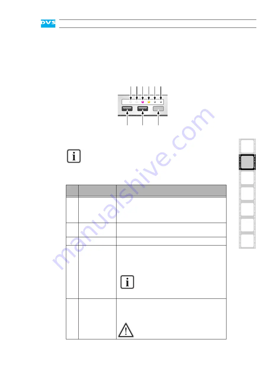
2.2.6 Operation Items
With the operation items at the system’s front the hardware of the
SpycerBox can be controlled (e.g. turned on or off). There you can also
find LEDs that allow you to assess the state of the DVS system as well
as USB connectors.
Figure 2-10: Operation items overview
The LEDs can be seen only when they are flashing because
they are located behind the white strip and thus not visible
when off.
Further information about what to do in case of an alarm can
be found in section “Troubleshooting” on page A-2.
No.
Item
Explanation
1, 2 LAN 1/2 LEDs Indicate that a valid network is connected to the
first/second LAN connection at the rear of the
system (see section “ATX Connector Panel” on
page 2-13).
3
alarm LED
This LED indicates that a hardware malfunction
has occurred.
4
DVD
Indicates accesses to the DVD drive.
5
mute
In case of a hardware malfunction a system
alarm turns on. By pressing this button the
alarm buzzer can be switched mute. Use a thin,
pointed object to press this button.
Some alarms (e.g. the one in case of a
hard disk failure) are independent of
the system alarm and cannot be
switched mute with the mute button.
6
reset
Resets your system and initiates a warm re-
boot. Use a thin, pointed object to press this
button.
Save your data before resetting the
system. Otherwise data may be lost.
1 2 3 4 5 6
7
8
9
Содержание DVS SpycerBox Flex
Страница 1: ...SpycerBox Ultra Flex Hardware Guide Version 3 0 Storage Solution SpycerBox Ultra Flex Hardware Guide ...
Страница 2: ......
Страница 6: ......
Страница 8: ......
Страница 36: ...2 18 SpycerBox Ultra Flex Hardware Guide ...
Страница 72: ...A 10 SpycerBox Ultra Flex Hardware Guide ...
Страница 76: ...I 4 SpycerBox Ultra Flex Hardware Guide ...