Arbitrary and Function Generator
R&S AM300
E-1007.9922.12
6-140
Operating manual, 02/2005
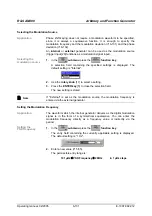
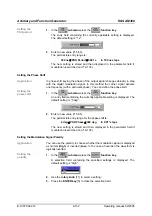
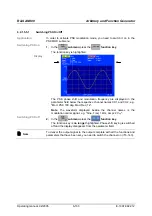
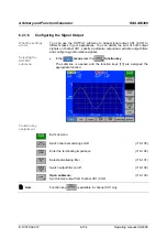
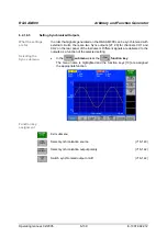
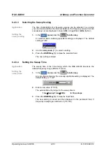
Selecting the Synchronization Source
Application
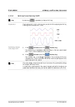
The following synchronization signal sources are available:
Comparator
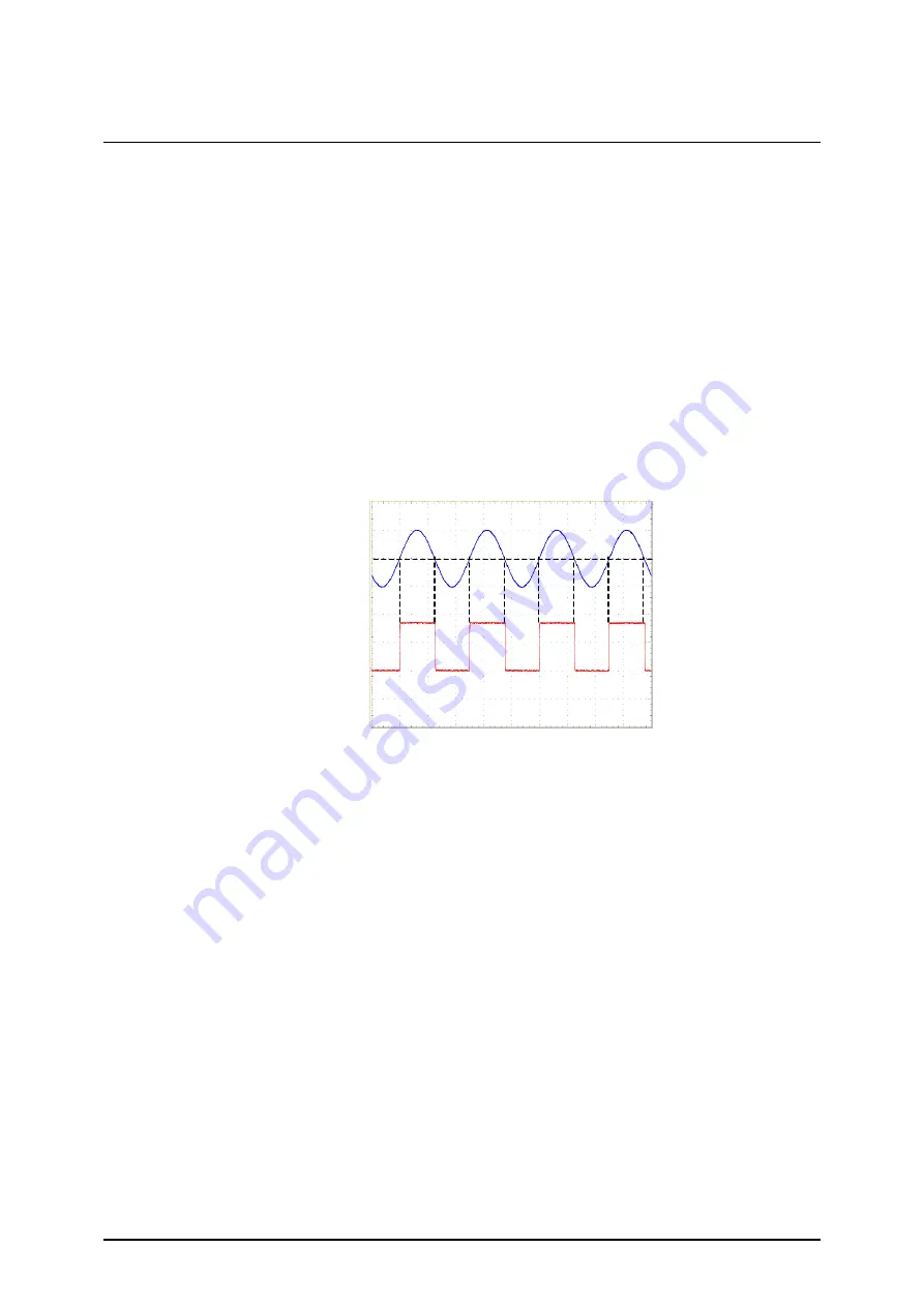
The outputs Sync1 and Sync2 are fed by analog comparators. Since
each channel has an analog comparator, the synchronization signals for
channel CH1 and channel CH2 can be different. The switching threshold
is fixed at the zero crossing. The comparator signals deliver relatively
jitter-free output signals across the whole frequency range. In situations
where frequencies are low, it may be advantageous to ignore the
comparator and instead take the feed from the synchronization outputs of
the MSB for the main phase accumulator ( below, Main accumulator).
All standard waveforms except Noise can generate a synchronization
signal. For the Sine waveform the synchronization signal has a duty cycle
of 50 %. For all other waveforms the duty cycle of the synchronization
signal is the same as that of the output signal.
Main accumulator
It is also possible to use the MSB of the main phase accumulator in each
channel as the source for the synchronization outputs. As in the case of
the comparators, the switching threshold is at the zero crossing, i.e. at 0
degrees and 180 degrees. Since the start phase is added on only after
the phase accumulator, the former makes itself felt as a phase difference
between the output signal and the synchronization signal.
At higher frequencies the jitter on the synchronization signal increases
sharply, making this method suitable only for the lower frequency range .
All standard waveforms except Noise and Pulse can generate a
synchronization signal. For the Sine waveform the synchronization signal
has a duty cycle of 1:1. For all other waveforms the duty cycle of the
synchronization signal is the same as that of the output signal.
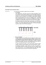
WAVEFORM
SYNC
Содержание AM 300
Страница 2: ...02 2005 ...


