Preparing for Use
R&S
®
SMU200A
24
Quick Start Guide 1007.9822.62 ─ 13
Note:
With exception of the Clock Out signal, the signals for triggering and control apply
for both paths.
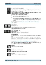
TRIGGER 1 / 2
TRIGGER 2
: Input for external triggering of digital modulations and standards and ARB.
TRIGGER 1
: Rear Panel Connectors for path A (option R&S SMU-B81) and path B
(option R&S SMU-B82).
This options are recommended for use of the instrument in a 19" rack. Installing the
instrument in a 19" rack requires a rack adapter or an adapter for telescopic sliders (refer
to data sheet for Order No.).
See also
chapter 2.3.2, "Placing or Mounting the Instrument"
2.3 Putting into Operation
This section describes the basic steps to be taken when setting up the R&S SMU for the
first time.
Shock hazard
Do not open the instrument casing. As a rule, normal operation of the instrument does
not require opening the casing. Observe the general safety instructions and regulations
at the beginning of the manual.
Risk of instrument damage
Note that the general safety instructions also contain information on operating conditions
that will prevent damage to the instrument. The instrument's data sheet may contain
additional operating conditions.
Putting into Operation
Содержание 1141.2005.02
Страница 27: ......
Страница 74: ...Preparing for Use R S SMU200A 57 Quick Start Guide 1007 9822 62 13 LXI Configuration ...
Страница 75: ......
Страница 95: ......
Страница 134: ...Manual Operation R S SMU200A 117 Quick Start Guide 1007 9822 62 13 Legend of Front Panel Controls ...
Страница 135: ......
Страница 140: ...Hardware Interfaces R S SMU200A 123 Quick Start Guide 1007 9822 62 13 Fig 1 2 BERT circuit diagram BERT Connector ...
Страница 141: ......
Страница 144: ...Index R S SMU200A 127 Quick Start Guide 1007 9822 62 13 Winbar 89 Windows XP 33 access 34 ...


