Preparing for Use
R&S
®
SMU200A
21
Quick Start Guide 1007.9822.62 ─ 13
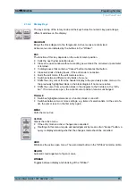
AC SUPPLY AND POWER SWITCH
When the R&S SMU is connected to the AC supply, it automatically sets itself to the
correct range for the applied voltage (range: see type label). There is no need to set the
voltage manually or change fuses.
The instrument comes with or without a power switch, depending on the design of the
otherwise technically equivalent power supply unit.
The power switch can be set to two positions:
●
0
The instrument is disconnected from the mains.
●
I
The instrument is power-supplied. It is either ready for operation (STANDBY) or in
operating mode, depending on the position of the ON/STANDBY switch on the instru-
ment front.
chapter 2.3.3, "Connecting the Instrument to the AC Sup-
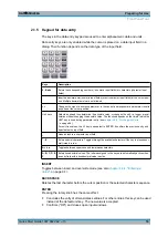
I OUT / Q OUT
(path A or path B)
Direct output or Differential (non-inverting) output for analog I/Q signal.
Option option R&S SMU-B16 is required.
I OUT BAR / Q OUT BAR
(path A or path B)
Differential (inverting) output for analog I/Q signal.
I/Q/DATA/CLOCK
Rear Panel Connectors for path A (option R&S SMU-B81) and path B (option R&S SMU-
B82).
This options are recommended for use of the instrument in a 19" rack. Installing the
instrument in a 19" rack requires a rack adapter or an adapter for telescopic sliders (refer
to data sheet for order number).
See also
chapter 2.3.2, "Placing or Mounting the Instrument"
Note:
Option R&S SMU-B16 (Differential Outputs) and options R&S SMU-B81/B82 can-
not be fitted both, because they use the same connectors.
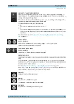
REF OUT
Output of internal reference signal.
REF IN
Input for external reference signal.
The external reference is used for both paths.
EXT MOD
Input for external analog modulation signals.
Rear Panel Tour
Содержание 1141.2005.02
Страница 27: ......
Страница 74: ...Preparing for Use R S SMU200A 57 Quick Start Guide 1007 9822 62 13 LXI Configuration ...
Страница 75: ......
Страница 95: ......
Страница 134: ...Manual Operation R S SMU200A 117 Quick Start Guide 1007 9822 62 13 Legend of Front Panel Controls ...
Страница 135: ......
Страница 140: ...Hardware Interfaces R S SMU200A 123 Quick Start Guide 1007 9822 62 13 Fig 1 2 BERT circuit diagram BERT Connector ...
Страница 141: ......
Страница 144: ...Index R S SMU200A 127 Quick Start Guide 1007 9822 62 13 Winbar 89 Windows XP 33 access 34 ...


