PowerFlex Digital DC Drive User Manual -
Publication 20P-UM001C-EN-P - July 2008
Programming and Parameters
3-19
MO
T
O
R CO
NTR
O
L
To
rq
Attr
ib
utes
926
[Filt Torq Cur]
First rate low-pass filter for Par 1193 [Torq Current Pct].
Default:
Min/Max:
Units:
0.100
0.001 / 0.250
s
1193
Spe
ed Fee
dbac
k
169
[Encoder PPR]
Number of pulses per revolution of the digital encoder. The
value of Pars 169 [Encoder PPR] and 162 [Max Feedback Spd]
must be set as indicated in
.
Default:
Min/Max:
1024.00
100.00 / 32770.00
162
414
[Fdbk Device Type]
The source of speed feedback.
•
1 “Encoder” = Digital encoder
•
2 “DC Tach” = DC analog tachometer
•
3 “Armature” = Internal measurement of the armature voltage
Default:
Options:
3 =
1 =
2 =
3 =
“Armature”
“Encoder”
“DC Tach”
“Armature”
455
[Spd Fdbk Error]
The maximum allowable speed feedback error expressed as a
percentage of the maximum output voltage set in Par 175
[Rated Motor Volt]. By means of Par 175 [Rated Motor Volt], Par
456 [Fld Weaken Ratio] and the motor nominal speed, a
relationship between motor speed and armature voltage is
obtained. If the difference is higher than the value set in Par 455
[Spd Fdbk Error], an “Encoder Loss” fault (F91) occurs.
Default:
Min/Max:
Units:
22
0 / 100
%
457
[Spd Fdbk Control]
Enables/Disables speed feedback control. This function controls
the speed feedback, where a comparison is made between the
armature voltage and the speed value read by the encoder or
tachometer. When the value set in Par 455 [Spd Fdbk Error] is
signaled, the fault message “Encoder Loss” (F91) displays. This
function is automatically disabled when the armature feedback
has been selected (Par 414 [Fdbk Device Type] = 3 “Armature”).
Default:
Options:
1 =
0 =
1 =
“Enabled”
“Disabled”
“Enabled”
455
458
[SpdReg FB Bypass]
Enables/Disables an automatic switch to armature feedback
when the “Encoder Loss” (F91) fault occurs due to an encoder
or tachometer feedback loss. When this parameter is set to
“Enable”, Par 478 [Spd Loss Flt Cfg] must be set to 1 “Alarm”.
After an automatic switch to armature feedback, the speed
regulator works with Pars 459 [SpdReg Kp Bypass] and 460
[SpdReg Ki Bypass] and the D derivative part of the speed
regulator is automatically excluded. Pars [SpdReg Kp Bypass]
and [SpdReg Ki Bypass] must be properly tuned. An automatic
switch to armature feedback can only be accomplished when
running the motor with constant field current.
Default:
Options:
0 =
0 =
1 =
“Disabled”
“Disabled”
“Enabled”
478
562
[Anlg Tach Gain]
Fine scaling of the speed feedback received from the DC analog
tachometer (Par 414 [Fdbk Device Type] = 2 “DC Tach”). The
voltage feedback value received from the tachometer is
multiplied by this value.
Default:
Min/Max:
1.00
0.90 / 3.00
563
[Anlg Tach Zero]
Offset scaling of the feedback circuit.
Default:
Min/Max:
Units:
0.00
–/+20.00
RPM
File
Gr
oup
No.
Parameter Name & Description
See
page 3-2
for symbol descriptions
Values
Related
A
A
A
!
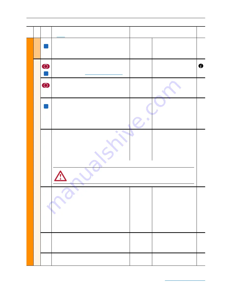
ATTENTION: If speed feedback control is disabled (Par 457 [Spd Fdbk Control] set to 0
“Disabled” and Par 414 [Device Type] is set to 1 “Encoder”, the motor could run at excessive
speed or become damaged, which could result in personal injury or destruction of equipment.
Содержание PowerFlex series
Страница 1: ...USER MANUAL Firmware Version 1 006 2 001 PowerFlex Digital DC Drive ...
Страница 190: ...PowerFlex Digital DC Drive User Manual Publication 20P UM001C EN P July 2008 A 22 Supplemental Drive Information Notes ...
Страница 292: ...Index 24 PowerFlex Digital DC Drive User Manual Publication 20P UM001C EN P July 2008 ...
Страница 293: ......


