Rockwell Automation Allen-Bradley PanelView Series Скачать руководство пользователя страница 5

Rockwell Automation Publication VIEW-IN001C-EN-P - April 2018

5

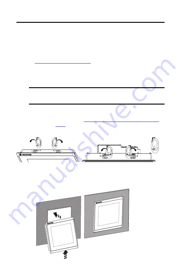
PanelView Mounting Levers

Mount the Terminal in a Panel

Follow these steps to mount your PanelView terminal in a panel cutout.

1. Use the cutout template that is shipped with your terminal to mark the cutout 

dimensions and cut the hole in the panel.

See 

Panel Cutout Dimensions on page 8

 if you do not have the cutout template.

2. Verify that the sealing gasket is present on the terminal.

This gasket forms a compression type seal. Do not use sealing compounds.

3. Insert and stabilize the PanelView terminal in the panel cutout. 

a. Depending on your terminal model, insert the mounting levers in the top corner 

slots by using the orientation in 

Mounting Lever Orientation and Lock Sequence


that starts on 

page 3

b. Rotate the round side of the mounting levers toward the panel.

c. Tilt the terminal toward the panel cutout and guide the terminal upward into the 

cutout; make sure that the mounting levers stay intact.

IMPORTANT

Catalog number 2711P-RMCP mounting levers are used only with PanelView 5310, 
PanelView 5500, PanelView 5510, and PanelView Plus 7 Performance terminals

(1)

Do not use these mounting levers with other PanelView terminals. 

(1)

These mounting levers do not work on PanelView Plus 7 Performance stainless steel terminals.

TIP

The mounting levers in the top corner slots help to stabilize the terminal in the 
panel while you install the remaining mounting levers.

Flat 

Side

Round 

Side

10.4-in. terminal shown in this example.

Содержание Allen-Bradley PanelView Series

Страница 1: ...5310 terminals PanelView 5500 terminals PanelView 5510 terminals SummaryofChanges This publication contains new and updated information as indicated in the following table Topic Page Summary of Change...

Страница 2: ...is oil or other chemicals Make sure thatmetal cuttings do notenter any components that are already installed in the panel and that the edges of the cutout have no burrs or sharp edges Failure tofollow...

Страница 3: ...Side 4 6 5 2 1 3 4 2 4 7 5 6 8 3 1 3 1 10 7 6 5 8 12 1 in TouchWidescreen 10 Levers 9 in TouchWidescreen 8 Levers 7 in TouchWidescreen 6 Levers 6 in Touch Screen 4 Levers 2 4 9 Flat Side Flat Side IM...

Страница 4: ...5510Terminals 3 1 10 6 8 7 5 10 4 in Keypad andTouch 12 1 in Touch Only 10 Levers PVP7 PV5500 and PV5510Terminals 2 4 9 2 4 9 7 11 5 6 12 8 10 3 1 15 in Touch Only 12 Levers PVP7 PV5500 and PV5510Term...

Страница 5: ...rs in the top corner slots by using the orientation in Mounting Lever Orientation and Lock Sequence that starts on page 3 b Rotate the round side of the mounting levers toward the panel c Tilt the ter...

Страница 6: ...levers varies for each terminal size 4 Slide and rotate each lever to a notch that is one or two positions greater than the final lock position start with the first lever in the sequence For example i...

Страница 7: ...ting levers to their final position 6 Inspect all mounting levers to make sure each is in the correct locked position The notch on the outside of mounting lever shows its locked position These two vie...

Страница 8: ...42 5 59 237 9 33 Touch 142 5 59 184 7 24 7 in Touch 150 5 90 210 8 25 9 in Touch 162 6 38 252 9 92 10 4 in Keypad and touch 224 8 82 335 13 19 Touch 224 8 82 269 10 59 12 1 in Touch 218 8 58 312 12 28...

Отзывы: