94
Rockwell Automation Publication 1734-UM013J-EN-P - July 2014
Chapter 5
Configure the Module in a GuardLogix Controller System
Configure the Safety Analog Input Channel Operation
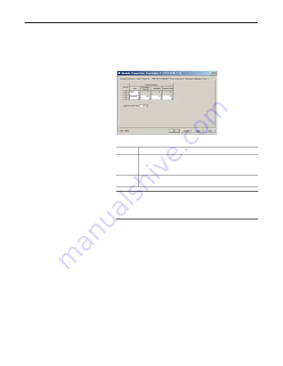
Follow this procedure to configure the safety analog input channels.
1.
From the Module Properties dialog box, click the Safety Input
Configuration tab.
2.
Assign the Operation Type.
3.
If you chose Equivalent, you must also assign a Discrepancy Time, from
0…65,530 ms in 10 ms increments.
This is the amount of time the two channels can be different from each
other (larger than the Deadband value) before a discrepancy error is
declared. A discrepancy time setting of 0 ms means that the channels in a
dual configuration can be discrepant for an infinite amount of time
without a fault being declared, effectively eliminating the usefulness of
dual channel mode.
4.
Configure a Deadband for the paired safety analog inputs.
The deadband can be any value from 0…32767 (engineering units) in
increments of 1. When the paired input values exceed the deadband
tolerance for longer than the Discrepancy Time, a discrepancy fault
occurs.
5.
If desired, configure a Channel Offset for the paired safety analog inputs.
Choose
Description
Single
Inputs are treated as single channels. Dual-channel safety inputs can be configured as two
individual, single channels.
IMPORTANT:
Use single-channel mode when you intend to use the GuardLogix safety
application instructions.
Equivalent
Inputs are treated as a dual-channel equivalent pair. The channels must match within the
discrepancy time or an error is generated.
IMPORTANT
If you are using a Dual-channel Analog (DCA) safety instruction in
your application program, you must configure the 1734-IE4S module
for single-channel operation. Analog input pairs are then evaluated
as pairs and compared to each other in the application logic.
TIP
Configure a deadband value for applications that use two sensors to
measure the same variable; otherwise, spurious trips may occur.
Содержание Allen-Bradley 1734-IB8S
Страница 1: ...POINT Guard I O Safety Modules Catalog Numbers 1734 IB8S 1734 OB8S 1734 IE4S User Manual ...
Страница 4: ...4 Rockwell Automation Publication 1734 UM013J EN P July 2014 Summary of Changes Notes ...
Страница 10: ...10 Rockwell Automation Publication 1734 UM013J EN P July 2014 Table of Contents ...
Страница 14: ...14 Rockwell Automation Publication 1734 UM013J EN P July 2014 Preface Notes ...
Страница 22: ...22 Rockwell Automation Publication 1734 UM013J EN P July 2014 Chapter 1 POINT Guard I O Overview Notes ...
Страница 150: ...150 Rockwell Automation Publication 1734 UM013J EN P July 2014 Chapter 8 Replacing POINTGuard I O Modules Notes ...
Страница 180: ...180 Rockwell Automation Publication 1734 UM013J EN P July 2014 Appendix C Specifications Notes ...
Страница 186: ...186 Rockwell Automation Publication 1734 UM013J EN P July 2014 Appendix D Safety Data Notes ...
Страница 190: ...190 Rockwell Automation Publication 1734 UM013J EN P July 2014 Appendix E Configuration Parameters Notes ...
Страница 204: ...204 Rockwell Automation Publication 1734 UM013J EN P July 2014 Appendix G History of Changes Notes ...
Страница 211: ......


