Rockwell Automation Publication 1715-UM001J-EN-P - December 2020
89
Chapter 2 Installation Instructions
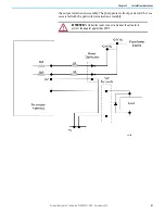
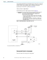
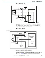
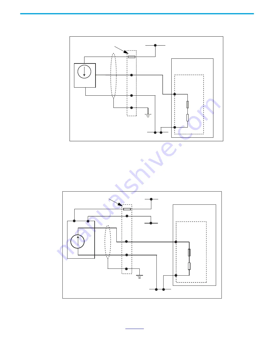
Figure 47 - Three-wire Analog Input
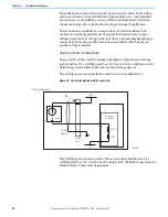
This field loop connection method is used for four-wire analog field devices.
Fit a suitably rated fuse, “F3” in each circuit to help protect the field wiring,
terminal block and 4mA -20mA current generator.
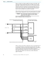
Figure 48 - Four-wire Analog Input
Field Wiring of Analog Input Termination Assemblies
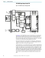
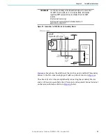
The termination assembly routes each analog input through a circuit similar to
that shown in
. The input channel is protected with a 50 mA fuse.
Shield
Required
Terminal
Blocks
OV
Termination
Assembly
+24V DC
4…20 mA
3-Wire Analog Input
50 mA
120 Ω
32117 M
F2
Shield
Required
Terminal
Blocks
OV
Termination
Assembly
-V
+V
4…20 mA
4-Wire Analog Input
50 mA
120
Ω
32118 M
F3
Содержание Allen-Bradley 1715-AENTR
Страница 10: ...10 Rockwell Automation Publication 1715 UM001J EN P December 2020 ...
Страница 114: ...114 Rockwell Automation Publication 1715 UM001J EN P December 2020 Chapter 2 Installation Instructions Notes ...
Страница 134: ...134 Rockwell Automation Publication 1715 UM001J EN P December 2020 Chapter 4 Digital I O Operation Notes ...
Страница 200: ...200 Rockwell Automation Publication 1715 UM001J EN P December 2020 Chapter 6 Configure the Redundant I O System Notes ...
Страница 244: ...244 Rockwell Automation Publication 1715 UM001J EN P December 2020 Chapter 9 Redundant I O System Diagnostics Notes ...
Страница 272: ...272 Rockwell Automation Publication 1715 UM001J EN P December 2020 Appendix C Reconfigure a Module Online Notes ...
Страница 290: ...290 Rockwell Automation Publication 1715 UM001J EN P December 2020 Appendix G History of Changes Notes ...
Страница 296: ...296 Rockwell Automation Publication 1715 UM001J EN P December 2020 ...
Страница 297: ...Rockwell Automation Publication 1715 UM001J EN P December 2020 297 Redundant I O System User Manual ...

