2-10
Installation and Wiring
Control Wiring Considerations
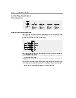
Wiring Diagram Key
General Control Wiring Advisories
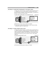
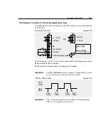
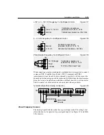
The figure below lists the control wiring requirements for all two wire control input
modes (P46 - [Input Mode] settings 1 and 4 – 9). The requirements specific to each
input mode are shown separately for that mode.
➊
Run input must be maintained. After a stop command, either a Run Forward or Run Reverse input
must be toggled to start the drive.
➋
Internal 12V supply. Contact closure or open collector input required. Refer to Appendix A for solid
state control input specifications.
➌
If both Run Forward and Run Reverse inputs are closed at the same time, an undetermined state
could occur.
➍
Control signal cable length is highly dependent on electrical environment and installation practices.
To improve noise immunity, TB3 Common must be connected to ground terminal/protective earth.
For control wiring installations greater than 15 meters (50 feet) in length, an optional 24V DC
interface module is recommended. See Appendix A for ordering information.
N.O.
Momentary
Contact
N.O.
Maintained
Contact
N.C.
Maintained
Contact
N.C.
Momentary
Contact
Shielded
Wire
➋
56
7
8
➍
➊➋➌
➊➋➌
TB3
Содержание Allen-Bradley 160 SSC Series
Страница 12: ...1 6 Getting Started End of Chapter ...
Страница 58: ...5 20 Parameters and Programming End of Chapter ...
Страница 66: ...A 4 Specifications End of Chapter ...
Страница 75: ...Accessories and Dimensions B 9 Drilling Template A Figure B 10 ...
Страница 76: ...B 10 Accessories and Dimensions Drilling Template B Figure B 11 ...
Страница 82: ...C 6 CE Conformity End of Chapter ...
Страница 87: ......


