


Features and technical data
Installation, use and maintenance manual – TS 2000
7
1
1
FEATURES AND TECHNICAL DATA
1.1
FEATURES
1.1.1
Operation
The TS 2000 gas-fired convector is an independent heat-
ing appliance with sealed combustion chamber and natu-
ral draught with balanced flow.
It has been designed to be installed inside the room to be
heated.
It can operate either with natural gas (G20) and LPG (G30/
G31) (gas-fired convector belonging to category II
2H3+
ac-
cording to EN 613).
The combustion air intake and the flue gas outlet take
place outside the installation room by means of two coax-
ial pipes. Therefore the appliance must be positioned on
an external perimeter wall.
The dual function of air intake and flue gas exhaust per-
formed by the coaxial duct does not allow for connection
to traditional flues.
The operation principle of the TS 2000 gas-fired convec-
tor is based on a convective motion of room air that pass-
es through the gas-fired convector from bottom to top,
is heated and diffused into the room through the upper
grille.
For this reason it is important not to obstruct
the air outlet by placingclothing or any other
objects over the outlet grille; always keep cur-
tains, chairs or any other furniture at least 30
cm away from the heater.
The operation of the appliance, which is very simple in
itself, is made completely automatic by the thermostatic
regulation: in fact, the user only requires the preliminary
ignition operation and the choice of the desired tempera-
ture (set on the thermostatic control knob).
The sealed combustion chamber is the best guarantee of
safety for the environment in which the gas-fired convec-
tor is installed: there is no possibility of the products of
combustion leak, nor is the oxygen necessary for combus-
tion taken from the environment. The appliance, once in-
stalled in accordance with the installation standards, does
not require any ventilation openings in the room.
A flame detection device using a thermocouple interrupts
the gas supply in the event of an accidental shutdown.
1.1.2
Mechanical components
▶
Sealed combustion chamber.
▶
High-efficiency aluminium alloy heat exchanger.
▶
Ø 100/60 mm coaxial combustion air intake and flue
gas exhaust pipes.
▶
External flue gas terminal in aluminium alloy.
▶
Casing in epoxy powder-coated sheet metal.
▶
Support bracket for wall mounting.
1.1.3
Control and safety devices
▶
Gas valve providing the following functions:
burner ignition
flame monitoring
heat exchanger temperature probe control
▶
Heat exchanger temperature control probe
▶
Piezoelectric ignition button
▶
Thermostatic control knob
1.2
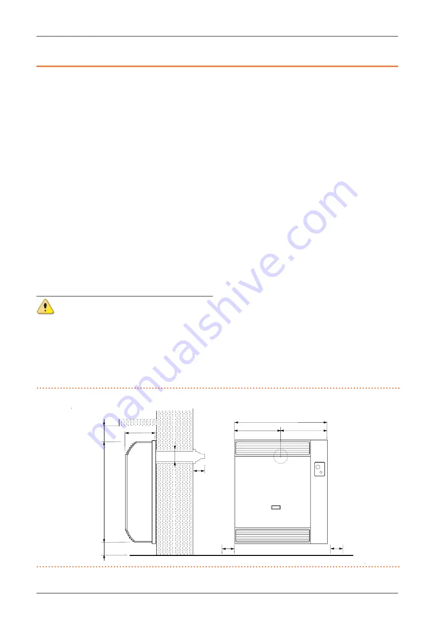
DIMENSIONS
Figure 1.1
Dimensions
170
100
480
190
290
100
1
00
< 3
50
>
50
100
100
577