


Electrical installer
28
4
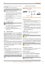
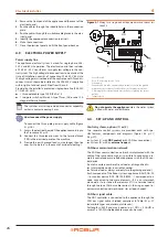
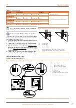
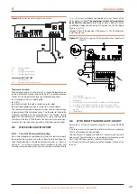
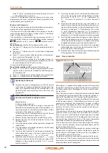
Figure 4.4
CAN bus connection for systems with multiple single units
DDC
Dir
ec
t Dig
ital C
on
trol
SCH
S61
con
troller
J1
Jumper CAN bus in boar
d
J21
Jumpers CAN bus on DDC boar
d
H,L,GND
D
ata sig
nal wir
es (r
ef
. cables table)
A
Ter
minal node c
onnec
tion (3 wir
es; J1
and J21 = "
closed")
B
In
ter
media
te node c
onnec
tion - (6
wir
es; J1 and J21 jumpers = "
open")
C
CAN bus cable shield
D
Insula
ting tape t
o pr
ot
ec
t the shield of
the CAN bus cable
E
Ey
elet t
er
minal and fixing scr
ew
5
2
N
230
V
MAIN
N
L
BOX
IGN.
3
6
W
R
Y
F4
0
F3
F1
24ac2
0 V
1
4
JP1
1
FL
24 ac1
TL
JTAG
SRT2
JP12
A2
P6
TF
A1
GND
SP1
H
L
P8
SCH
F2
PUMP 230
V
N
J1
0
CONTACT
BK
WH
BR
FAN
L
NO
TA2
TCN
THMF
THRF
TG
TA
TA1
SP1
P6
JP12
JP1
1
4
1
F1
F3
0
F4
Y
R
W
6
3
IGN. BOX
L
N
2
5
A1
TF
A2
TL
24 ac1
FL
0 V
24ac2
P8
H
L
GND
SCH
TA
TG
THRF
THMF
TCN
NO
FAN
BR
WH
BK
CONTACT
J1
0
F2
SRT1
SRT2
JTAG
TA1
TA2
MAIN 230
V
N
L
L
N
230
V
PUMP
L
SRT1
1
2
3
4
4
3
2
1
5
6
DDC
GND
JUMPER J1
A
P8
L
H
B
A
GND
JUMPER J1
P8
L
H
GND
H
L
JUMPER J21
P8
H
L
GND
C
D
E
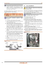
Place the CLOSED J21 Jumpers (Detail A) if the node is terminal
(one connected CAN bus cable section only), or OPEN (Detail
B) if the node is intermediate (two connected CAN bus cable
sections).
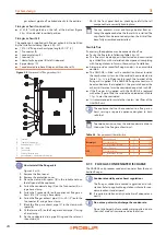
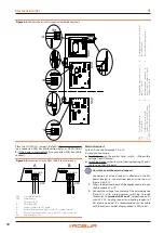
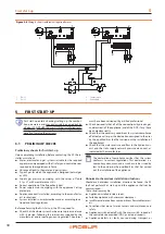
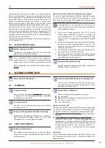
Figure 4.5
Connection of the CAN bus cable to the control panel
DDC
Direct Digital Control
GND
Common data
L
Data signal LOW
H
Data signal HIGH
J21
Jumpers CAN bus on DDC board
A
Detail of "terminal node" case (3 wires; J21 = jumper "closed")
B
Detail of "intermediate node" case (3 wires; J21 = jumper "closed")
P8
CAN port/connector
DDC
DDC
GND
H L
JUMPER J21
P8
GND
H L
JUMPER J21
P8
B
A
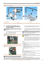
External request
System (2) see also Paragraph 1.6
It is required to arrange:
▶
Enable device (e.g. thermostat, timer, switch, ...) fitted with a
voltage-free NO contact.
▶
Switching devicewinter/summer (heating/cooling, W and Y
contacts on the S61 board).
How to connect the external request
Connection of external request is effected on the S61
board located in the electrical panel inside the unit
(Figure 4.6
p. 29):
1.
Access the electrical board of the appliance according to
the Procedure 4.2
2.
Connect the voltage-free contact of the external device
(Detail CS), with winter/summer switching, through
three wires, to
terminals R, W and Y
(respectively: com-
mon 24 V AC, heating request and cooling request) of
S61 electronic board. It is recommended to use a cable
with the correct number of color-coded 18 AWG wires.


