ROBOTIQ RWC-UR-KIT Скачать руководство пользователя страница 39

Robotiq Wrist Camera Vision System for Universal Robots

Instruction Manual

Robotiq inc. © 2016

39

6.1.1 Center of Mass and Moment of Inertia

The coordinate system used to calculate the moment of inertia and center of mass of the Wrist Camera is the base of the Camera which correspond to the

UR tool flange reference [0,0,0].

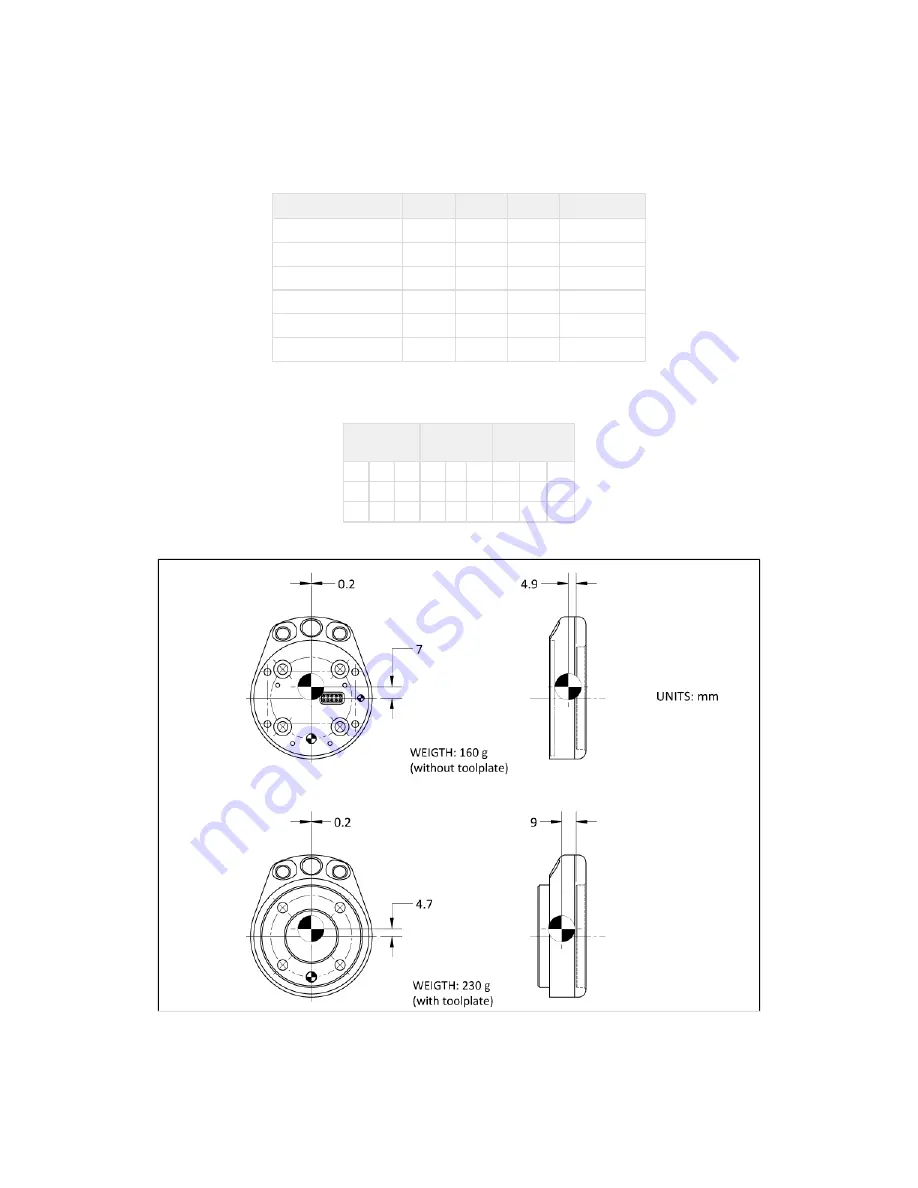
Here is the approximate position for the center of mass. It has been calculated for the camera itself and for combinations with other Robotiq products. The

camera's tool plate is included when the gripper is not mounted on the Wrist Camera.


Combination

x (mm)

y (mm)

z (mm)

Mass (grams)

-

0

5

9

230

FT 300

0

2

30

530

2-Finger 85

0

1

58

975

2-Finger 140

0

1

66

1040

FT 300 and 2-Finger 85

0

1

77

1275

FT 300 and 2-Finger 140

0

1

85

1340


Here is the approximate moment of inertia matrix for the Wrist Camera:

Inertia Matrix

Metric value

(kg * mm ) 

2

Imperial value

(lb * in ) 

2

Ixx

Ixy

Ixz

111

0

0

0.38

0

0

Iyx

Iyy

Iyz

0

70

3

0

0.24 0.01

Izx

Izy

Izz

0

3

165

0

0.01 0.56


Figure 6.1.1.1: Center of Mass with and without the toolplate.

Содержание RWC-UR-KIT

Страница 1: ... ROBOTIQ INC 2016 Get the latest version of the manual at support robotiq com ...

Страница 2: ...nes on Snapshot Position 25 4 2 Snapshot Position Wizard 26 5 Object Teaching 28 5 1 Guidelines on Object Teaching 29 5 2 Cam Locate Node Teach Object Wizard 30 5 2 1 Part Contours 33 5 2 2 Detection score threshold setting 34 5 3 Programming with a Cam Locate Node 35 6 Specifications 37 6 1 Mechanical Specifications of Wrist Camera 38 6 1 1 Center of Mass and Moment of Inertia 39 6 2 Electrical r...

Страница 3: ...uct improvements modifications or changes in specifications If such modification is made the manual will also be revised see revision information See the latest version of this manual online at http support robotiq com 2016 11 16 Updated specifications section 6 Updated installations instructions section 4 Added Troubleshooting instructions section 9 1 2016 08 26 First release ...

Страница 4: ...sal Robots This system will use the Robotiq Wrist Camera mounted on any of the UR3 UR5 UR10 using a CB3 1 controller or greater For a list of provided components with your Robotiq Wrist Camera kit Universal Robots for please consult the section UR Scope of Delivery Figure 1 1 Schematic representation of the Robotiq Wrist Camera Vision System hardware Robotiq Wrist Camera Described in details in su...

Страница 5: ...f view of the Camera and thus the workspace See for section 4 details on how to teach the Snapshot Position Figure 1 2 Schematic representation of the Robotiq Vision System Snapshot Position and workspace concepts Snapshot Position the robot pose use to take snapshots from the Wrist Camera Workspace the area of interest for the Vision System it is defined by the Camera s field of view object the o...

Страница 6: ... the object location process See secti for details on the object location process on 5 Figure 1 3 object location process schematic representation Object to locate The object you want to locate with coordinates X Y and rotation Rz Camera Locate relative frame The reference frame updated by the Vision System to provide you with the object location Robot base frame The reference frame of the Univers...

Страница 7: ...image sensor with liquid lens Resolution 0 3 to 5 Mpx Frame rate 2 to 30 FPS Focus from 70 mm to infinity automatic control 2 sets of 3 LEDs Integrated lighting with automatic control Single high flex 10 meter pigtail cable USB 2 0 24V DC power ISO 9409 1 50 4M6 bolt pattern both sides Direct mounting on the UR Direct mounting of the 2 Finger Adaptive Gripper on the Camera Info The Robotiq Wrist C...

Страница 8: ...os in this document are representative examples and differences may exist between them and the delivered product Warning The operator must have read and understood all of the instructions in the following manual before handling the Robotiq Wrist Camera Vision System for Universal Robots The term operator refers to anyone responsible for any of the following operations on the Wrist Camera Vision Sy...

Страница 9: ...l safety measure for human robot collaboration Warning The Camera needs to be properly secured before operating the robot Do not install or operate a Camera that is damaged or lacking parts Never supply the Camera with an alternative current Make sure all cord sets are always secured at both ends at the Camera and at the robot Always respect the recommended keying for electrical connections Be sur...

Страница 10: ... for installation on a model UR3 UR5 or UR10 using CB3 1 controller only Universal Robots The unit may be used only within the range of its technical data Any other use of the product is deemed improper and unintended use Robotiq will not be liable for any damages resulting from any improper or unintended use Tip Section 4 1 will give you advice on what workspace should be usde or avoided will giv...

Страница 11: ...normally Section 3 4 guides you through the mechanical installation using the Wrist Camera and other optional parts Section 3 5 describes the required electrical set up of the Gripper its power source and cable management Section 3 6 guides you through the software installation Warning Before installing Read and understand the related to the Vision System safety instructions Verify your package ac...

Страница 12: ...st Camera on Universal Robots Combo of 2 Finger Adaptive Gripper and Wrist Camera for Universal Robots CUR AGC 085 RWC or CUR AGC 140 RWC Standard upon delivery Wrist Camera Kit for Universal Robots includes Robotiq Wrist Camera with 10m High Flex pigtail cable RWC CAM 001 16 Gig USB stick ACC USB 16G USB software licence dongle ACC USB DONGLE 4 ports USB hub ACC USB 4 HUB Calibration board ACC CA...

Страница 13: ...ed by a DC voltage source This power supply is not included with the Camera kit for UR Required power supply must match the Robotiq device The following table shows the specifications with regards to the power supply required to operate the Camera and the optional Robotiq Gripper SPECIFICATION VALUE Output voltage 24 V DC 10 Output current 1 A Overcurrent Recommended power supply with internal pro...

Страница 14: ...ondition Value Minimum storage transit temperature 30 C 22 F Maximum storage transit temperature 70 C 158 F Minimum operating temperature 0 C 32 F Maximum operating temperature 50 C 122 F Humidity Non condensing Others Lense must be free from dust soot and water Environment must be free from powerful electromagnetic interference Environment must be free from corrosive or explosive liquids or gases...

Страница 15: ...the tool plate RWC TOOL 062 on the camera Align the tool plate s indexing dowel pin correctly in the Wrist Camera Fix the desired end effector on the robot arm through the tool plate and the camera using M6 screws Fix the cable along the robot arm see Cable Management section Figure 3 4 1 Mechanical installation of the Wrist Camera kit for Universal Robots The end effector is not screwed in the ca...

Страница 16: ...era s indexing dowel pin properly in Universal Robots bolt pattern Fix the camera on the robot arm using the provided M6 X 12 LHCS screws and lock washers Mount the gripper directly on the Wrist Camera using the provided M5 X 35 SHCS and lock washers Fix the cable along the robot arm see Cable Management section Figure 3 4 2 Mechanical installation of the Combo of 2 Finger Gripper and Wrist Camera...

Страница 17: ...B 4 HUB inside the robot controller Connect the Wrist Camera s USB connector in the 4 ports USB hub Connect the licence USB dongle ACC USB DONGLE in the 4 ports USB hub Figure 3 5 2 4 ports USB hub connection Wrist Camera grounding is optional and is done via the robot ground The camera s indexing pin dowel is the ground connector Cable Management 2 Finger Gripper If mounting a 2 Finger Gripper on...

Страница 18: ...ation Before proceeding with the installation of the URCaps package make sure your Universal Robots software is up to date The PolyScope must be at least a 3 3 in order to install a URCap If a software update has to be performed after a new release please refer to to know how to update properly Section 3 6 3 Software version Both Vision Server and URCap package have to be the same version for inst...

Страница 19: ... manual Follow this procedure to install the Wrist Camera s Vision Server Go to and visit the Vision System page support robotiq com Download the latest Vision Server UCC zipped file Figure 3 6 1 1 Vision Server download on support robotiq com Make sure you unzip the content of the UCC file directly on the USB stick as shown Figure 3 6 1 2 File extraction on the provided 16 Gig USB stick Turn on t...

Страница 20: ...rver is being installed Wait for the popups to stop before going on to the next step Turn off the robot controller Turn the robot controller back on The Vision Server installation is complete Proceed with the Camera URCap installation in order to use the Vision system refer to Section 3 6 2 Do not unplug the 16 Gig USB stick or the licence USB dongle even after the installation is completed ...

Страница 21: ...com Download the latest UCC zipped file Figure 3 6 2 1 Download the URCap package from support robotiq com Unzip the content of UCC on a USB stick different from the provided 16 Gig USB stick containing the Vision server see Section 3 6 1 Connect the USB stick in the teach pendant or robot controller Follow these steps for URCap installation on Polyscope Vision Server Make sure the Vision Server h...

Страница 22: ...ogram Robot Polyscope s home page Go in the tab then in Installation Camera After the installation tap Start Camera This step only has to be done after an installation or update The ouput image from the camera will appear on the teach pendant s screen Camera If the output image does not show in the Camera tab tap Stop camera Wait for the Vision server to be stopped and tap Start camera Gripper URC...

Страница 23: ...te the software package Turn off the robot controller Remove the 16G USB stick and connect it to a PC You will need to format the USB device using FAT32 Unzip the latest Vision Server UCC zipped file from on the USB device support robotiq com Using another USB stick unzip the URCap UCC ziped file Turn on the robot controller Connect the 16G USB stick in the 4 ports USB hub A series of red popups w...

Страница 24: ... for details on the field of view Calibration Boards For UR5 and UR10 Along with your kit you will have the calibration board used for UR5 and UR10 robots part number ACC CALIB BOARD If you loose or damage your board you can print the following file For UR3 If you are using a UR3 you will need a different calibration board As of today it is not provided and you will need to print the following fil...

Страница 25: ...he workplace will increase the workspace but will increase the minimum size of objects to locate Angle of the camera Snapshot position should consider the Camera angle Robotiq greatly recommends to have the Camera perpendicular to the surface Be as close as possible to perpendicular avoid reflections Object should be seen from the top view not from the side Calibration board Snapshot position does...

Страница 26: ... 2 Calibrate Place the appropriate calibration board in the field of view of the camera Remember to use the appropriate board according to your robot model The board orientation should match the screen landscape orientation Make sure the Camera see the whole board Tap to begin calibration Calibrate The Vision System will center on the board and take 18 poses of the board process takes roughly 3 mi...

Страница 27: ...rge as a square of the grid Hide grid Hides the grid of the camera s field of view Save position Saves the robot position for the Snapshot Position This is the position from which the robot will do the part detection Calibrate Starts the calibration procedure The robot will move automatically to defined positions for the calibration Cancel Cancels the calibration procedure while it is running Re c...

Страница 28: ...napshot Position is defined as per steps of section 4 Have the object to teach in hand Have a few samples to test during the last step of the object teaching process Reminder A Camera Locate node will be used for a single object Object teaching is linked to the Snapshot Position if you want to change Snapshot Position you will have to do the object teaching process again You can teach many objects...

Страница 29: ... the camera in the background photo step of if is better to leave a margin section 5 2 around it as shown in figure 5 1 1 Figure 5 1 1 Choosing the appropriate background Ambient conditions During the teaching process it is important to have stable lighting At run time lighting can fluctuate can also be compensated with object detection threshold The Wrist Camera has integrated lighting your appli...

Страница 30: ...ave Place your part in the field of view and test locating with the run time environment Tap to do so Test locating object If the object is found you will see Object located appear with the detection score If no object is found you will have a pop up message that says Model not found You can adjust the with the and buttons Detection threshold Detection threshold is a key feature to ensure you have...

Страница 31: ...ep of the Object Teaching wizard Scan Tap to start the scanning procedure The robot will move automatically around your object Cancel Tap to cancel the scanning procedure while it is running Test locating object Tap to test locating an object the Vision System will search the field of view for your object Detection Threshold Tap to lower the Detection Threshold setting Detection Threshold Tap to i...

Страница 32: ...Robotiq Wrist Camera Vision System for Universal Robots Instruction Manual Robotiq inc 2016 32 ...

Страница 33: ...atures spotted on one photo but not on the actual one will be outlined with red lines During wizard step 4 Test and Save When testing the localization of parts Part contour and recognized features outlined with blue lines Features spotted on one photo but not on the actual one will be outlined with red lines Info Blue contour should match the part shape at all time features withing the part may or...

Страница 34: ...e success rate by 5 increments tapping the icon above the false detection threshold Try localization between each increments If you are not able to detect the part decrease the threshold by 5 increments tapping the icon in order to detect the part on the whole workplane This procedure ensures the best robustness regarding the part detection throughout the workplane If it is not possible to define ...

Страница 35: ...me updated by the Camera Locate Without moving your part teach your way points according to it s position When you are done with the movements relative to the part you can insert another Move node selecting a movement that is not relative but absolute base frame and do normal movements This process will give you A set of MoveL movements relative to the part orientation A set of MoveJ moveL etc mov...

Страница 36: ...Robotiq Wrist Camera Vision System for Universal Robots Instruction Manual Robotiq inc 2016 36 Figure 5 3 1 Template program for a Camera Locate pick place application ...

Страница 37: ...140 Adaptive Grippers Section 6 1 mechanical specifications of the Wrist Camera Dimensions Maximum load Center of mass Moment of inertia Section 6 2 electrical rating performance specifications of the Wrist Camera Electrical supply Resolution FPS Section 6 3 Vision System specifications Field of view Part size Reminder The following manual uses the metric system unless specified all dimensions are...

Страница 38: ... Added height without tool plate for use with 2 Finger Gripper 13 5 mm Global thickness without tool plate 22 4 mm Added height with tool plate 23 5 mm Global thickness with tool plate 29 5 mm Table 6 1 1 Wrist Camera s mechanical specifications Photographic sensor Respecting Universal Robots s axes system the photographic sensor s is located at 0mm 35 7mm 0 1mm of the tool flange on which the cam...

Страница 39: ...ra itself and for combinations with other Robotiq products The camera s tool plate is included when the gripper is not mounted on the Wrist Camera Combination x mm y mm z mm Mass grams 0 5 9 230 FT 300 0 2 30 530 2 Finger 85 0 1 58 975 2 Finger 140 0 1 66 1040 FT 300 and 2 Finger 85 0 1 77 1275 FT 300 and 2 Finger 140 0 1 85 1340 Here is the approximate moment of inertia matrix for the Wrist Camer...

Страница 40: ... here are the electrical specifications of the Camera Specification Value Operating supply voltage 24 V DC 20 Quiescent power minimum power consumption 1 W Maximum power 22 W Communication interface USB 2 0 Here are the Wrist Camera s specifications Specification Value Maximum resolution 5 Mpx at 2 fps 2560 X 1920 Maximum frame rate 30 fps at 0 3 Mpx 640 X 480 Active array size 2592 X 1944 Focus r...

Страница 41: ...d of view Specification Value UR3 UR5 UR10 Maximum field of view cm 36 x 27 64 x 48 100 x 75 Minimum field of view cm 10 x 7 5 10 x 7 5 10 x 7 5 Tip Snapshot Position will determine the field of view notice that the calibration step position does not have to be the same as Snapshot position Thus you can have a small field of view then move back for calibration step Info Field of view is FoV determ...

Страница 42: ...iew s dimension The minimum is 10 no matter the robot or the field of view size Figure 6 3 2 Maximum and minimum part size The part must not be higher than its smallest dimension width or length maximum of 1 1 ratio Figure 6 3 3 Maximum part height Info Part height ratio is taken between the maximum part height at any point and the minimum dimension present on part contour width or length ...

Страница 43: ...hould use a background that has a high color contrast with the part to be detected You must choose colors that are apart horizontally on the HSV cone shown below Therefore a change in value intensity only does not represent a good contrast There has to be a great difference in hue and saturation to obtain a good object model from the object teaching wizard Figure 6 3 4 HSV color cone ...

Страница 44: ...mera along with alcohol to clean the lens Background clean You workspace should be kept as constant as possible Depending on your application you should occasionally clean the workspace Note If your workspace background changes after the object teaching process at run time object localization performance could decrease Tip The Vision System is able to compensate for some differences during run tim...

Страница 45: ...a tool plate for ISO 9409 1 50 4M6 pattern Universal Robots RWC TOOL 062 Replacement calibration board ACC CALIB BOARD Replacement 10m High Flex pigtail cable for Wrist Camera CBL COM 2069 10 HF 4 ports USB 2 0 hub splitter ACC USB 4 HUB 16 Gig USB stick ACC USB 16G Replacement software licence USB dongle for Wrist Camera ACC USB DONGLE Universal Robots Screw Kit for Wrist Camera ACC SCREW KIT RWC...

Страница 46: ...D status Versions To view the Vision server Camera URCap and Camera firmware versions proceed with the following From a Robot program go in the Installation tab Choose Camera Go in the About tab The versions will appear Make sure they are the latest release and that they are both updated simultaneously Note More details to come ...

Страница 47: ...eck the USB cable connection and the software package versions Solid blue and red at the same time The Camera is in fault or booting Wait for the booting process to be completed If the LED stays solid blue and red disconnect the Camera s USB cable and power cycle it The red LED should be solid red Reconnect the USB cable The LED should turn solid blue when communication is established with the Vis...

Страница 48: ...be liable for damages resulting from the use of the Robotiq Wrist Camera or Robotiq Vision System nor shall Robotiq be responsible for any failure in the performance of other items to which the Wrist Camera is connected or the operation of any system of which the Vision System may be a part Exclusions This warranty excludes failure resulting from improper use or installation normal wear and tear a...

Страница 49: ...inc 2016 49 11 Contact www robotiq com Contact us Phone 1 888 ROBOTIQ 762 6847 01 418 380 2788 Outside US and Canada Fax 1 418 800 0046 Technical support and Engineering extension 207 Sales extension 122 Head office Robotiq 966 chemin Olivier Suite 325 St Nicolas Québec G7A 2N1 Canada ...

Страница 50: ...Robotiq Wrist Camera Vision System for Universal Robots Instruction Manual Robotiq inc 2016 50 A Harmonized standards declarations and certificates Note Details coming soon ...

Отзывы: