background image

b. To check your driver version :

l

With the Gripper unplugged

l

From the UR teach pendant screen, click the " Gripper" button

i. Driver version will be shown

ii. If Gripper button is not displayed, driver package is not properly installed, see instruction from

the

2. Driver is installed but Gripper cannot be controlled :

a. If Gripper LED is not blue, follow the steps in the first section above

b. If Gripper LED is blue, driver is installed with the latest available version, contact [email protected]

9.2.2. Vacuum Gripper verification

If you are not able to attain the desired vacuum level or if a diminution of the vacuum level occurs, verify:

l

The suction cups status

l

That the air path is clean and not obstructed (including the manifold)

l

If a filter cleaning is necessary

90

Содержание PALLETIZING SOLUTION

Страница 1: ...Robotiq Palletizing Solution for Universal Robots Instruction Manual ROBOTIQ PALLETIZING SOLUTION robotiq com leanrobotics org Original Notice 2020 Robotiq Inc...

Страница 2: ...ions 22 3 4 Mounting and Installation 23 3 5 OtherGrippers 47 3 6 InstallationforUniversalRobots 49 3 7 URCap Package 49 3 8 License Agreement 55 4 Operation 58 4 1 Starting Up 58 4 2 LightsStates 58...

Страница 3: ...e 85 8 Spare Parts Kitsand Accessories 86 9 Troubleshooting 87 9 1 Palletizing Solution except the AirPickGripper 87 9 2 AirPickVacuum Gripper 88 10 Warranty 91 11 Harmonized Standards 93 11 1 Applied...

Страница 4: ...s made the manual will also be revised see revision information See the latest version of this manual online at support robotiq com 2020 12 16 l Update of the safety section l Update of the installati...

Страница 5: ...thout prior written consent from Robotiq Under copyright law copying includes translation into another language or format Information provided by Robotiq in this document is believed to be accurate an...

Страница 6: ...ed with the linear axis pallet sensors and status lights The extra reach gripper bracket is also included in the Solution to extend the AirPick Gripper of 200 mm from the robot tool flange The Materia...

Страница 7: ...ler All the components of the Solution are integrated and controlled via the linear axis controller It allows simultaneous motion of the axis and the robot during palletizing motion 1 1 4 Pallet Senso...

Страница 8: ...n be installed directly under the Vacuum Gripper Each Robotiq Suction Cup System includes a bracket a manifold air nodes port plugs bumpers tubing and additional suction cups Fig 1 2 Suction cup syste...

Страница 9: ...obot tool flange This way the Robotiq Palletizing Solution will be able to palletize boxes on large size pallets Please refer to the Extra Reach Bracket section for more details about the limitations...

Страница 10: ...rder to use only one suction cup the single cup can be mounted right in the port of the vacuum generator 1 2 2 Auxiliary System with Multiple Suction Cups l A standard Suction Cup System can be attach...

Страница 11: ...tion Diagrams The following diagrams explain the logical operation of the Palletizing Solution based on the operator s actions and all responses coming out from them such as signals pallet and box sen...

Страница 12: ...Palletizing Solution Instruction Manual 12...

Страница 13: ...tion l Installation l Control l Maintenance l Inspection l Calibration l Programming l Decommissioning The present section is based on the following international standards and technical specification...

Страница 14: ...n emergency conditions and not for normal condition stop Info The Solution is intended to be used with a UR10 or UR10e from Universal Robots Info Always comply with local state province and or federal...

Страница 15: ...for the suction cups Caution It is the installer operator s responsibility to ensure that all local safety measures and regulations are met The following non exhaustive list presents risks that must...

Страница 16: ...d the object will not be lost l If no object is detected the Vacuum Gripper will go into a standby state 2 seconds after the e Stop button is pressed The AirPick Vacuum Gripper that comes with the Rob...

Страница 17: ...Power W Speed mm s Force N Power W Speed mm s Normal mode Up to safety limits up to 250 up to 1000 up to 5000 2400 690 nominal 500 Protective stop 0 Stop Cat 2 Safeguard stop 0 Stop Cat 2 N A Stop Cat...

Страница 18: ...ot information please refer to the Universal Robots documentation l For the linear axis o Maximal stopping time for Category 1 500 ms o Maximal stopping time for Category 0 100 ms o Travelled distance...

Страница 19: ...mended environmental conditions l Do not operate the Palletizing Solution or even turn on the power supply before the device is firmly anchored and the machine area is cleared Make sure that the air s...

Страница 20: ...rate heat l Always lift heavy objects with your legs not your back If you can not lift an object alone ask for help or find another method to move it 3 1 Scope of Delivery l 1 x robot base including o...

Страница 21: ...m hex key o 4 mm hex key o 6 mm hex key o 10 mm hex key l Not included o Lifting equipment min capacity of 200 kg such as a gantry crane overhead crane jib crane chain block or forklift with a proper...

Страница 22: ...Water No Other l Free from corrosive liquids or gases l Free from explosive liquids or gases Table 3 1 Environmental and operating conditions of the Robotiq Palletizing Solution Caution Use of the Rob...

Страница 23: ...the robot arm An air fuse should also be installed 3 3 2 Depressurizing the Supply Line In order to safely depressurize the supply line the air supply must first be shut off Then if no lockout valve i...

Страница 24: ...lear when lowering the column onto the base Failure to do so could result in serious injuries or death 1 Open the crate by removing the top and four 4 sides using a drill 2 Cut all straps that retain...

Страница 25: ...alletizing Solution Instruction Manual 6 Lift the foot base unscrew the piece of wood under the foot base Remove the piece of wood and descend the Solution slowly and carefully see the picture below 2...

Страница 26: ...7 Position the column vertically Use the lift point to rotate the column Caution Be careful not to pinch the cables If necessary secure them before lifting and placing the column on the base 26...

Страница 27: ...truction Manual 8 Lift and place the column onto the base Info A hook is present at the top of the column Use it to lift the column 9 Secure the base with the column using the four 4 M10 screws Tighte...

Страница 28: ...machine damage serious injuries or death You can mount the solution at the place of your choice However to finalize it you will have to move it to its final location There are two possibilities to se...

Страница 29: ...zing Solution Instruction Manual 3 4 4 Mechanical and Electrical Installation Tip A minimum of two people is recommended for theses steps Base Cover 1 Remove the cover that will allow the cable manage...

Страница 30: ...or UR10e cobot are required for the installation The cobot is not included in the Robotiq Palletizing solution For robot installation few cables need to be wired The figure below resumes the identific...

Страница 31: ...2 mm l For e Series use screws M8 x 25 mm 2 Unclip the mounting bracket of the cable management system that is right beside the column 3 Press the robot power cable into the tube up to the column Ther...

Страница 32: ...able management system Info Refer to the cable routing system manufacturer installation instructions for more details Universal RobotsController Installation 1 Remove the four screws on the top of the...

Страница 33: ...truction Manual Power CablesConnections 1 Plug the power cable output of the linear axis controller into the URcontroller 2 Plug the robot power cable into the URcontroller 3 Connect the Teach Pendant...

Страница 34: ...e 2 Then continue to channel the cable through the column and the base and bring it out from the other extremity of the base Info The safety signals wires sticking out of the linear axis controller ar...

Страница 35: ...ick Vacuum Gripper installation It will ensure proper functioning of the solution The goal is to properly align the column with the base by placing the robot wrist at a specific position at the same t...

Страница 36: ...e base reference to 333 35 mm TCP must be 0 Warning Move the robot slowly and watch the movement to avoid collisions 6 Turn the column clockwise so that the side of the robot wrist touches the side of...

Страница 37: ...dditional reach is needed install the extra reach gripper bracket on the robot tool flange using four 4 M6 screws and tooth lock washers and align properly with the dowel pin Info Install the bracket...

Страница 38: ...enerator 2 Secure the manifold by inserting screws and tooth lock washers in a cross pattern to properly compress the O ring of the gen erator 3 Insert each suction cup with an O ring into an air node...

Страница 39: ...5 Elbow 60 Wrist 1 80 Wrist 2 90 Wrist 3 90 1 Attach the cable routing system onto the robot as illustrated in the figure below l Install the four 4 straps and attach the tube in the three first strap...

Страница 40: ...tighten the assembly Make sure to only let the coupling cable connector out 4 Connect the coupling cable to the connector visible at the end of the cable management 5 Install the Igus R Lock at the e...

Страница 41: ...d ISO 8573 1 class3 4 3 We recommend using a local pressure regulator with a filter and air dryer 9 Use the spiral cable sleeve to keep the air tube and the coupling cable together 10 Plug the other e...

Страница 42: ...into a USB port 2 Plug the Ethernet USB converter cable into a USB port 3 Plug the Ethernet cable into the Ethernet socket on the top of the linear axis controller 4 Pass the other extremity of the ca...

Страница 43: ...pplied by Robotiq for Safeguard connections l If the safeguard is not used add jumpers between pin 1 2 and 3 4 l Do not forget to connect the safety reset wire white color according to your safety set...

Страница 44: ...ct the USB cable into a USB port of the robot controller The figure below illustrates the Vacuum Gripper pigtail connector from the coupling GRP CPL 062 or AGC CPL XXX 002 the device cable on the robo...

Страница 45: ...aff If you use the anchors provided with the Solution it should be installed in 28 MPa 4000 psi undamaged concrete minimum l If you choose to use other anchors each anchor should be able to withstand...

Страница 46: ...t 1 Position the Solution at its final position Caution Make sure your layout is good and that all distances are respected See the Appendixsection 2 Drill the six 6 holes with the provided drill bit 3...

Страница 47: ...the Safetysection 3 5 Other Grippers It is possible to use a gripper other than the AirPick Vacuum Gripper If another gripper is used it is important to validate that its shape is within the gripper...

Страница 48: ...that an extra reach bracket is used A rectangular prism is then added at the end of the bracket according to the rules mentioned above Bracket representation Height Width Length Direction 31 5 mm 75...

Страница 49: ...refer to the Installing URCap Package section to configure the Palletizing Solution properly before operating and programming the device 3 7 URCap Package Robotiq provides the user with a Universal R...

Страница 50: ...ip of URCaps and extract them on the root of a blank USB stick l Insert the USB stick in the URteach pendant or controller l On the teach pendant tap the triple bariconin the upper right corner of the...

Страница 51: ...patible with the Palletizing URCap package l Go to www support robotiq com select Browse byproduct l Click on your Robotiq product page and then Universal Robots l Click on Software Robotiq product UR...

Страница 52: ...l Restart PolyScope to complete the URCap installation By doing so you accept the License Agreement that is detailed in the URCap Information text box see below for the License Agreement l When PolyS...

Страница 53: ...l On the teach pendant tap the triple baricon l Tap Settings l Select System in the navigation pane on the left l Select URCaps l In the Active URCapsbox select the URCap to uninstall l Tap the minus...

Страница 54: ...iesrobots l Go to Setup Robot l Tap URCapsSetup l In the Active URCaps box tap the URCap to unin stall l Tap the minus buttonto uninstall the URCap l Restart PolyScope to complete the uninstallation p...

Страница 55: ...5 Licensor s Products means those products developed by the Licensor in the course of the Licensor s Business 6 UR s Products means those products developed by URin the course of the UR s Business 7 L...

Страница 56: ...out warranty of any kind THE LICENSOR AND THE LICENSOR S AUTHORIZED REPRESEN TATIVES DO NOT WARRANT THAT Software WILL BE FREE OF ERRORS AND YOU ACKNOWLEDGE THAT THE EXISTENCE OF ANY SUCH ERRORS DOES...

Страница 57: ...ensor and the End User for any purpose concerning this Agreement or the parties obligations hereunder shall be brought exclusively in a court of com petent jurisdiction sitting in the judicial distric...

Страница 58: ...howVacuum Toolbar checkbox 4 Select the digital input for box sensors 5 Test the box sensor and the digital input Tap Installation I O Setup and place an object in front of the box sensor to test to v...

Страница 59: ...ot has not established the communication yet with the linear axis controller l Tap Installation URCaps Copilot Linear Axisand click on Scanbutton Bothsame Solid red An axis error happened l Tap Instal...

Страница 60: ...e pallet is not detected and the system is idle l Place a new pallet Left and or Right Solid White When l The linear axis is activated and brake is released l A program is running without Pal letizer...

Страница 61: ...r License Dongle into the USB hub in the URcontroller Make sure your Copilot license is activated a Tap Installationtab URCaps Copilot b On the Dashboard tab the Copilot License activation will appear...

Страница 62: ...is ready 5 1 1 Palletizer node 1 Before you start programing your features make sure that your Robotiq Palletizing Solution is set this way 2 On the Teach Pendant tap the Program button 3 Select URCa...

Страница 63: ...Info You will have to configure four 4 parametersto program your Palletizing Solution 5 To begin click on BOX to set your box dimensions 6 In the Boxdimensionsparameter you have to set the box s l Wi...

Страница 64: ...tion the robot tool flange connector on side A same side as the robot wrist as shown in the picture above b Make sure to align the TCP with the center of the box c Once you are done click on Ok l You...

Страница 65: ...dimensionsparameter you will have to a Select the desired pallet l Right or left l Both pallets b Determine the dimensions of the l Front l Side l Height 10 The PALLET and BOX parameters are now comp...

Страница 66: ...he number and sequence of your layer s boxes l You can create and use a maximum of two patterns the PatternA and the PatternB Make sure to select the desired ones l Click on Edit to configure your pat...

Страница 67: ...he pattern you chose A B or both l Click on the buttonto add boxes l Use the arrows to move and position the boxes on the pallet as desired 14 Three of your parameters are now set Complete your config...

Страница 68: ...te at program startup is checked by default If you unselect it then the system will consider that the pallets are empty 16 If you start a program where the checkbox is filled by default you can have e...

Страница 69: ...Palletizing Solution Instruction Manual 17 All your Palletizer parameters have been configured You are now ready to start your Solution 69...

Страница 70: ...values of the gripper input registers While the control is very simple some behaviors deserve a better explanation The Vacuum Gripper can work in two different mode the Automaticand Advanced modes For...

Страница 71: ...unless specified all dimensionsare inmillimeters The following subsections provide data on the various specifications for the Robotiq Palletizing Solution 6 1 Technical dimensions 6 1 1 Linear AxisBas...

Страница 72: ...6 1 2 AirPick Vacuum Gripper Fig 6 1 AirPick general dimensions 72...

Страница 73: ...Palletizing Solution Instruction Manual 6 1 3 Extra Reach Bracket 73...

Страница 74: ...6 1 4 Bracket for two 2 Suction Cups Fig 6 2 Two air nodes bracket s dimensions 74...

Страница 75: ...Palletizing Solution Instruction Manual 6 1 5 Bracket for 4 SuctionsCups Fig 6 3 Four air nodes bracket s dimensions 75...

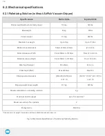
Страница 76: ...6mm From 12 in to 40 in Pallet dimensions Depth From 300mm to 1219mm From 12 to 48 in Pallet height empty Min 25mm Min 2 in Pallet height filled Max 2200mm Max 87 in Shipping crate dimensions 2380 950...

Страница 77: ...I Maximum Feed pressure 7 bar 101 526 PSI Air consumption at optimal pressure 135 9 SLPM 35 9 gpm Maximum torque permissible by custom suction cup bracket 150 Nm 110 lbf ft Air supply connection type...

Страница 78: ...2 suctioncups 0 30 5 40 42 20 0 0 127 7 890 AirPick with4 suctioncups 0 20 4 30 48 70 0 0 127 7 1115 AirPick without suctioncup extra reachbracket 143 2 4 20 15 30 200 0 72 2 1128 AirPick with1 suctio...

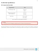
Страница 79: ...ac 6 4A at 240Vac Fig 6 5 Linear Axis Controller electrical specifications Warning The linear axis controller is CE marked and cCSAus certified Any modification will void the certification The followi...

Страница 80: ...80...

Страница 81: ...site 6 3 2 AirPick Vacuum Gripper Info For all information about AirPick Vacuum Gripper specifications please consult its instruction manual available on our support website 6 3 3 Universal RobotsCont...

Страница 82: ...scraps dust grease etc l Interaction with operated parts sharp or rough l Dynamics of the operation accelerations Caution Always turn off the Palletizing Solution and depressurize the air supply tube...

Страница 83: ...before the lubrication Info Recommended lubricant LUB KC1 Ball Screw and Bearing Guide Lubrication Lubrication of the axis should be done every 2 years considering a typical use of 80h week When lubri...

Страница 84: ...2 13 Wedge anchors 54 2 40 0 M8 Hoist ring 9 5 7 0 M8 Robot carriage interface 20 0 14 8 M8 Lifting bracket Linear axis interface 9 5 7 0 Motor Coupling Coupling collar 8 0 5 9 Table 7 1 Torque Settin...

Страница 85: ...al parts including the guide rail of the linear axis with a soft cloth as required Cleaning agents include all non abrasive media Caution Do not use compressed air to clean the Vacuum Gripper Doing so...

Страница 86: ...sbase including o 1 x Mechanically welded assembly o 1 x Vertical axis 1500mm o 1 x Motor o 1 x Control Motion Box PLC Drive safety relay o 4 x Pallet sensors o 2 x Status Lights o 1 x Cable managemen...

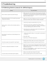
Страница 87: ...bigger box width and or length l Make sure you have started your program with the pallet viewer representing your current situation Robot triggers a protective stop when placing a box on the first la...

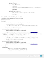
Страница 88: ...the communication and power cycle the Gripper The LED should turn solid red when powered b While powered with red LED connect the communication LED should turn solid blue when connection is establishe...

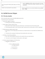
Страница 89: ...talled but Gripper cannot be controlled 1 If Gripper LED is not blue follow the steps in the first section above 2 If Gripper LED is blue URCap is installed with the latest available version contact s...

Страница 90: ...pper cannot be controlled a If Gripper LED is not blue follow the steps in the first section above b If Gripper LED is blue driver is installed with the latest available version contact support roboti...

Страница 91: ...ntenance specified in the Maintenance section l Usage respects recommended payload force acceleration and speed specified in the Mechanical specifications section During the warranty period Robotiq wi...

Страница 92: ...Robotiq shall not be liable for damages resulting from the use of the Palletizing Solution nor shall Robotiq be responsible for any failure in the performance of other items to which the Palletizing...

Страница 93: ...allation safety measure and normal usage must be respected The following standards have been applied ISO 12100 2010 Safety of machinery General principles for design Risk assessment and risk reduction...

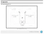
Страница 94: ...Palletizing Solution Instruction Manual 1 2 Appendix 1 2 1 Anchoring pattern Fig 12 1 Palletizing Work Zones Schema...

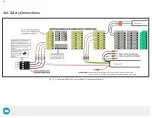
Страница 95: ...1 2 2 Safety Connections Fig 12 2 Universal Robots Controller Safety Connections Schema 95...

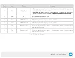
Страница 96: ...of the protected area 2 Brown 0V 0V link between both electrical enclosures 3 Green URE Stop Status 1 E Stop status signal when a emergency signal is applied to EI0 4 Yellow URE Stop Status 2 E Stop...

Страница 97: ...1 888 ROBOTIQ 762 6847 01 418 380 2788 Outside USand Canada Technical support and engineering option 3 Sales option 2 Head office Robotiq 966 chemin Olivier Suite 500 St Nicolas Qu bec G7A 2N1 Canada...

Отзывы: