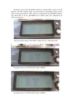


Under normal circumstances, the LED2 will light, while in the excellent case,
only LED1 will light.
Lighting up of LED3 represents that you need to adjust the position of airborne
equipment.
Step three, adjust the position. The objects that need to be adjusted are the EMI
interference sources. There are two ways to search the EMI interference sources:
The first method is to press EMISCAN and power up the receiver. While moving
the position of the onboard devices, observe the signal strength. When interference
sources are close to the antenna, there will be higher signal strength displayed.
The second method is to set the transmitter to the DEBUG mode and make range
test. In extreme range, the RX light on the receiver will be blinking irregularly. At
this time, the signal is in intermittent state. When the receiving antenna is near the
EMI interference sources, the RX will become worse or even the signal will be
blocked then RX turns to standby mode.
When the interference sources are found, adjust the position of the receiving
antenna and the receiver. The farther from the interference sources the better. The
wireless video transmitter had better use a separate battery and do not be connected on
the same ground with the receiver battery. When using fuel engine, please pay
attention to avoid shocks. When using the gasoline engine, please pay attention to the
high voltage interference.
Step four, tips for test flight. Check the autopilot, return switch's settings, whether
the R4047NB20 is set with failsafe and whether the T4047NB20 needs to be shut
down sync with your transmitter.
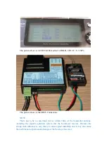
Step five, if necessary, you can use the following simple method to test whether
the output RF of T4047NB20 is strong enough. Take one cable with plastic cap
removed and insert a LED. Pinch the metal conductor with your finger, and keep the
coil close to the transmitter antenna. If the power of transmitter is more than 2W, the
LED will light. The LED is considerably bright under 5W.
Quick User Guide
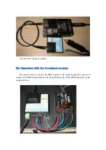
Control process: Take the FUTABA T12FG for example. The T12FG transmits
signals to R6203SB, and R6203SB's SBUS signal is transmitted to the signal
acquisition system, and then to T4047NB20, subsequently T4047NB20 transmits
UHF radio frequency signal to R4047NB20, finally R4047NB20 outputs 18 channel
PWM signal to each servo.
1, Connect the transmitter antenna.
2, The transmitter's DIP switches are all OFF.
3, Connect DATA1 with the signal acquisition system.