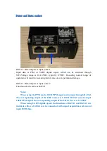
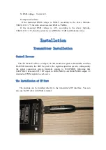
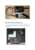
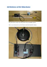

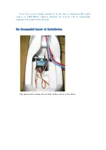

The picture above shows the PWM connection, in which CH12 connects to he IP
interface. the 12FG settings allows the sync-transmit of 4047NB20 system and the
12FG. Under sync-transmit, 12FG powers on coupled with the 4047NB20 starting.
And when 12FG is off, the 4047NB20 move to IDLE mode. The configuration of
12FG is as followed:
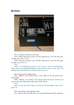
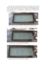
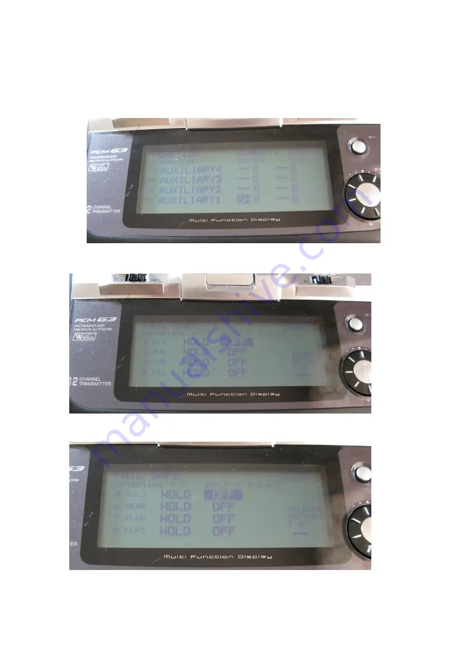
The picture above shows FUNCTION settings. CH12 is controlled by SH.
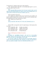
The picture above is 1-4CH Fail-Safe setted to HOLD.
The picture above is 5-8CH Fail-Safe setted to HOLD.