background image

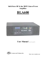
Solid State HF & 6m 500W Linear Power 

Amplifier 


BLA600 

User Manual 

http://www.rmitaly.com 

Costruzioni Elettroniche 

Rev 1.0  June 2017 


Содержание BLA600

Страница 1: ...Solid State HF 6m 500W Linear Power Amplifier BLA600 User Manual http www rmitaly com Costruzioni Elettroniche Rev 1 0 June 2017 ...

Страница 2: ...SWR Level Bargraph 4 Enter key 5 Data key 6 Data key 7 Navigate key BLA600 Front Panel 8 LED Warning Protection 9 LED TX Indicator 10 Standby Operate Key 11 Manual Band Select Keys 12 AC Mains ON OFF Switch 13 RF Deck Cooling Intake 14 LPF Board PSU Cooling Intake 2 ...

Страница 3: ...ono RCA Type 5 PTT Input Connector Phono RCA Type 6 Antenna 1 Output Connector SO239 7 Antenna 2 Output Connector SO239 8 Antenna 3 Output Connector SO239 9 AC Input Voltage Selection 10 Exhaust Grille LPF PCB 11 Exhaust Grille PSU 12 RTX Input Connector SO239 13 RF Deck Exhaust Grille 14 RF Ground Stud M5 3 ...

Страница 4: ... by a heavy duty linear power supply with 115 230 and 240 volt AC input options but utilises an efficient active bridge rectifier and high grade fil ter capacitors to provide the amplifier with a very low noise and robust 50V DC supply The RF deck has a large heat sink and copper heat spreader which provides a very efficient cooling system with separate fans for the RF deck and LPF board power sup...

Страница 5: ...7 Antenna Output Selection 9 8 Operation 10 9 Modulation Modes 13 10 Menu 13 1 ALC 14 2 TEMP 16 3 BRIGHTNESS 16 4 CONTRAST 17 5 CW QSK 17 6 STANDBY STB PARAMETERS 18 7 OPERATE OP PARAMETERS 18 8 DEFAULT 19 9 ESC 19 10 Protection 20 Start Up Errors 20 Operational Errors 21 11 Grounding 23 12 Warranty 25 13 Specifications 26 5 ...

Страница 6: ...y implemented by means of a short and low impedance connection usually by means of a heavy copper strap This will decrease noise problems in reception and eliminate the possibility of high RF voltages appearing on the chassis of the amplifier and other metallic equipment in the station that the operator may come into contact with This can be due to unbalanced antennas or static build up Do not use...

Страница 7: ...sunlight for long periods The rear panel of the amplifier should be no closer than 15cm from a wall to allow the exhaust air to freely exit the amplifier for optimum cooling efficiency As the amplifier is quite heavy make sure that the supporting structure is capable of supporting the weight Connection The BLA600 requires the following connections in order to function The output of the transceiver...

Страница 8: ...T input if the standard microphone PTT is not used The PTT input _ is a close to ground system which is compatible with all modern radios that use open collector or open drain outputs for further information consult the instruction manual for the transceiver or your dealer on how to connect an external linear amplifier The PTT Input to the amplifier requires an RCA Phono type plug The cable should...

Страница 9: ... begin to flash and then after 3 seconds a beep will be heard confirming the saved selection Each time the same band is returned to the last memorised selection will be returned In Standby mode pressing the band key of any band will display the currently memorised Antenna output on the LCD display The antenna output may also be changed temporarily without saving the selection This can be useful in...

Страница 10: ...mplifier in Standby or connected in line but physically switched off a maximum of 100W may be used With the amplifier switched off antenna 1 is the active output With the amplifier switched on but in Standby the output will be determined by the frequency of transmission and the programmed Antenna output 1 2 or 3 for that frequency As shipped from the factory all bands are set to ANT 1 output For t...

Страница 11: ...er This is best carried out either in a constant carrier mode CW or FM to provide a constant output level You can then see what input power is required to drive the amplifier to 500W So long as you are operating into a 50 ohm resistive load antenna there is no problem to remain in TX whilst doing this procedure for some time if your dummy load is suitably rated if doing this into a radiating anten...

Страница 12: ...iently rated or a problem with the antenna itself not being able to support high power Antennas that have matching networks or baluns at the feed point or trapped antennas where maybe an ATU is used to cover both CW and SSB sections of the band Make sure that these components are rated for the power being used Sudden increases in VSWR can also indicate arcing on variable capacitors or component fa...

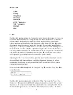
Страница 13: ...switching The only difference between this feature and standard is that there is no display of the two chosen parameters on the LCD during the transmission cycle E G Drain voltage and Heatsink temperature etc However the amplifier is still monitoring all of these parameters in background and nothing changes regarding protection of the amplifier See menu 5 CW QSK for further details 10 Menu To ente...

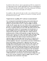
Страница 14: ...ge that is suitable for all modern transceivers If using the ALC menu make sure that the BLA600 ALC Output on the rear panel is connected to the radios ALC input See your radios instruction manual for further details Adjusting the ALC level is a one time operation and when the adjustment is made the amplifier is in Bypass and is not amplifying the signal However to reduce unnecessary interference ...

Страница 15: ...the maximum ALC output voltage from the amplifier under fault conditions which will be used to reduce the input power to 0W When the power has been set to 0W Press Enter The ALC is now set and you will be returned to the menu list You can now continue within the menu or exit by any one of the 3 ways explained previously ALC Max trimmer Clockwise rotation as seen from the rear panel reduces ALC vol...

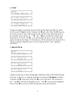
Страница 16: ...sor will briefly appear to indicate the change At this point you will be returned to the menu list You can now continue within the menu or exit by any one of the 3 ways explained previously 3 BRIGHTNESS Change the intensity of the LCD backlight LED Power Meter LED SWR Indicator There are 3 options Low Medium and High Select menu 3 Brightness with the Navigate key a then press Enter key to access t...

Страница 17: ...r key to save the current selection and return to the menu list 5 CW QSK To minimise the RTX switching time for maximum performance in Full Break In mode especially if sending 25 WPM this menu should be activated Use the Navigate key a to select 5 CW QSK and then press the Enter key to access the menu Use or _ keys to select On or Off Then press the Enter key to save the current selection and retu...

Страница 18: ... return to the menu list 7 Operate Parameters During TX it is possible to monitor any of the following two Parameters on the LCD display Not in QSK Full Break In Mode Pin T1 Input Power and Heatsink Temperature at the transistor Pin T2 Input Power and Heatsink Temperature at the exhaust exit Pin Vd Input Power and Drain Voltage Pin Id Input Power and Drain Current T2 T1 Heatsink Temperature at the...

Страница 19: ...ifier to its factory settings All user modified parameters will be returned to default settings Use the Navigate key a to select menu 8 Default Press the Enter key to acess the menu Then press the key to activate the process and the following screen will be displayed This will take a few seconds to complete The amplifier will then reboot and return to Standby mode 9 Esc Exit the menu list Use the ...

Страница 20: ...t up self test should any of the following errors occur refer to the descripton below for explanation S1 Error with the cooling fans Check for obstructions and reboot the amplifier If the problem persists consult your dealer S2 Control of Vd drain voltage above 48V If this error occurs check that the AC supply voltage is within normal limits S3 Control of Vd drain voltage below 70V Again check tha...

Страница 21: ...em is an essential system for the correct function of the amplifier and further damage may occur if ignored Indicates that the power supply has overheated 62 C The error message will alert the user and there will also be an audible alarm of 5 short tones The Alarm indication LED b will illuminate The amplifier will not be operational until the temperature has fallen to an acceptable level at which...

Страница 22: ...l illuminate To clear the error check and adjust the antenna SWR then press the STB OPR d button to reset the amplifier This indicates excessive Drain Current The amplifier will emit 5 short error tones and the Alarm LED bwill illuminate Check that the amplifier is not being over driven and that the antenna SWR is within acceptable limits 2 0 1 Then press the STB OPR d button to reset the amplifie...

Страница 23: ...particular attention should be made to the fact that copper corrodes and as it does will lose its conductivity properties so a certain amount of maintenance will be required as time passes note copper braid stripped from coaxial cable is not a good idea If the cable is left intact with both the centre conductor and outer insulation present it can be used as a single conductor for ground connection...

Страница 24: ...microphones and CW keys computers rebooting monitors switching off RF distortion on the transmitted audio or RF getting into power supplies Multiple SWR meters at different points in the same line giving different readings Assuming of course SWR meters give same results at the same point in the line etc If a suitable RF ground cannot be made for example if the radio installation is not on the grou...

Страница 25: ... warranty directly If any repairs are carried out outside of an approved 3 service centre this will void the original warranty and 3 will not be responsible for any incurred charges The warranty will only be honoured if the amplifier has been used for it s intended purpose as described in the operation manual and it is returned with the original purchase receipt that the amplifier is transported i...

Страница 26: ...Gain Typical 14dB 1dB 80 10m Output Harmonic Spurious Distortion HF 45dB 6m 60dBc Input 50 Ohms Unbalanced UHF SO239 Female Input Matching 1 5 1 VSWR 160 6m Output 3x 50 Ohms Unbalanced UHF SO239 Female Teflon Insulator Gold plated terminal Supply Voltage 120 Vac 5 5 230 Vac 6 10 240 Vac 10 6 50 60Hz 1200VA max AC Input Fuse 5 x 20mm F LBC 250V Fast Blow 240Vac Supply 5A 230Vac Supply 6A 115Vac Su...

Страница 27: ...X Open Circuit RX Suitable for Open Drain Collector Relay switching Output 5V S C current 15mA in TX ALC Output Negative going voltage 0 to 10V Adjustable Dimensions 430mm x 142mm x 324mm Width x Height x Depth Weight 21 5 kg 27 ...

Отзывы: