Safety reliably produced.
© RLS Wacon analytics GmbH ∙ +49 (0)5121 28126 0 ∙
Subject to
change without notice
22
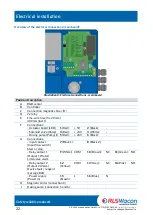
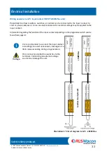
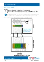
Illustration 8: Electrical connections - main board
Electrical installation
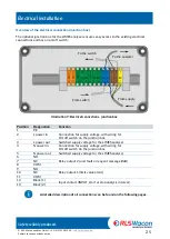
Overview of the electrical connections (main board):
Position Description
A
RGB sensor
B
Controller
C
Connection magnetic stirrer (H)
D
2x relay
E
Fine-wire fuse (5 x 20 mm)
400 mA (inert)
F
Connections:
- Actuator board (LED)
1
(Red):
+ 5V
2
(Black):
-
- Solenoid valve (Valve)
3
(Red):
+ 24V
4
(White):
-
- Dosing pump (Pump) (I)
5
(Red):
+ 24V
6
(Black):
-
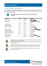
G
Connections:
- input contact
(Input flow switch)
Start or stop
7
(Black 1):
8
(Black 2):
- Relay output 1
(Output 1 Water)
Limit value alarm
9
(White): COM
10
(Brown): NC
11
(Green): NO
- Relay output 2
(Output 2 Alarm)
Device fault / reagent
message BoB
12
(Yellow):
COM
13
(Grey):
NC
14
(Pink):
NO
- Power supply
(Power in)
15
(Brown):
L
16
(Blue):
N
H
Magnetic stirrer (connection C)
I
Dosing pump (connection 5 and 6)
Содержание 32-074165
Страница 76: ......

