Sample Draw Combustible Gas Detector • 9
5. Route the cable or wires in conduit leading from the sample draw detector to the
recording or monitoring device and power.
6. Connect the cable shield to an available chassis ground at the device end.
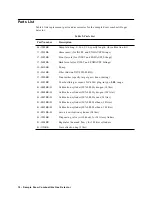
Figure 4: Wiring the Sample Draw Combustible Gas Detector
4/20 (F eedback)
Gr ound
+
WHT GR N BLK GN D
2 4V
+
_
L E L/ O2
AM P
P- AM P
4 / 20
GREEN
BLAC K
W HI TE
RED
PUMP ASSY
INTERNALLY
WIRED
24VD C
GN D
24V
4/20
RD
PUM P
PSW
TP
+
TP
ZERO
SPAN
GND
24V
4-20
RED
WHT
GRN
BLK
POWER/SIG
SENSOR
P/N 57-1050RK
REV. 0
NOT
USED
ON THIS
VE RS ION
H
N
1 15VAC
CG ND
PRES SURE SWITCH
INTERNALLY WIRED.
LEL Sam pl e Draw Housing
LEL DETECTO R IN
S AMPLE CHAMBER
(INT ERNALLY WIRED)
PCB IN SINGLE POINT
S AMPLE DRAWING
DETECTOR ASSY
Transmitte r, In terna lly Wired


