RIX Industries
MAN-2PS2B-N2
Page 16
1.
Install new O-ring expanders, compression rings and rider rings on the pistons.
2.
Compress the rings by hand to ensure the rings fully sit in the piston grooves.
3.
Slide the cylinders over the pistons, taking care not to extrude the rings.
4.
Install the heads per
Section 7.3
.
5.
Rotate the flywheel by hand several times to ensure parts are free. See
Section 7.9
for
piston clearance adjustment.
7.7
Piston Assembly
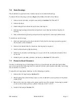
The 1st stage piston assembly is installed with the connecting rod and retaining cap. This assembly
must be removed to service the connecting rod and all bearings.
To remove the 1st stage piston assembly, reference
Figure 2
and use the following procedure:
1.
Remove both heads and cylinders per
Sections 7.3
and
7.5
.
2.
Rotate flywheel to position the 1
st
stage piston at top dead center.
3.
Remove hex screw on bearing plate.
4.
Gently slide assembly outward by pulling connecting rod off crankshaft, allowing neck of
piston to pass through slot in crankcase. Move assembly to a clean surface for further
disassembly.
5.
With a pair of snap ring pliers, remove snap rings from wrist pin bore.
6.
Remove the wrist pin—the piston may require heating or a press to do so.
7.
Remove the connecting rod.
8.
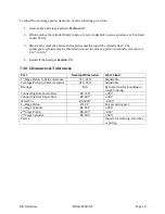
Clean and inspect piston, wrist pin, and bearings for wear or damage. Wear must be within
the tolerance specified in
Section 7.10
.
To reinstall the 1st stage piston assembly:
1.
Install the connecting rod, wrist pin, and snap rings in the 1
st
stage piston assembly.
2.
Install the assembly on the compressor crankshaft.
3.
Install bearing plate and hex screw to fully secure the assembly to the crankshaft. Hex screw
must be secured with a small amount of Loctite primer and threadlocker (RIX P/N’s: 35-
8595 & 35-7641) and torqued to 180 in-lbs.
4.
Reinstall cylinders and heads per
Sections 7.3
and
7.5
.
Содержание 2PS-H-N2
Страница 36: ...RIX Industries MAN 2PS2B N2 Page 28 FIGURE 1 COMPRESSOR CROSS SECTION FASTENER DETAIL...
Страница 37: ...RIX Industries MAN 2PS2B N2 Page 29 FIGURE 2 COMPRESSOR CROSS SECTION PUMP DETAIL...
Страница 38: ...RIX Industries MAN 2PS2B N2 Page 30 FIGURE 3 1ST STAGE VALVE DETAIL...
Страница 39: ...RIX Industries MAN 2PS2B N2 Page 31 FIGURE 4 2ND STAGE VALVE DETAIL...
Страница 40: ...RIX Industries MAN 2PS2B N2 Page 32 FIGURE 5 EXTERIOR FASTENER DETAIL...
Страница 41: ...RIX Industries MAN 2PS2B N2 Page 33 FIGURE 6 MOTOR AND CONTROL BOX MOUNTING...
Страница 42: ...RIX Industries MAN 2PS2B N2 Page 34 FIGURE 7 SUCTION PLUMBING DETAIL...
Страница 43: ...RIX Industries MAN 2PS2B N2 Page 35 FIGURE 8 INTERSTAGE PLUMBING DETAIL...
Страница 44: ...RIX Industries MAN 2PS2B N2 Page 36 FIGURE 9 FINAL DISCHARGE PLUMBING DETAIL...
Страница 45: ...RIX Industries MAN 2PS2B N2 Page 37 FIGURE 10 COOLING FAN SUB ASSEMBLY DETAIL...
Страница 46: ...RIX Industries MAN 2PS2B N2 Page 38 FIGURE 11 BELT INSTALLATION DETAIL...
Страница 47: ...RIX Industries MAN 2PS2B N2 Page 39 FIGURE 12 GUARD MOUNTING DETAIL...
Страница 48: ...RIX Industries MAN 2PS2B N2 Page 40 FIGURE 13 CONTROL BOX DETAIL 1 OF 2...
Страница 49: ...RIX Industries MAN 2PS2B N2 Page 41 FIGURE 14 CONTROL BOX DETAIL 2 OF 2...
Страница 50: ...RIX Industries MAN 2PS2B N2 Page 42 FIGURE 15 CONTROL BOX WIRING DIAGRAM...
Страница 51: ...RIX Industries MAN 2PS2B N2 Page 43 FIGURE 16 ELECTRICAL SCHEMATIC...
Страница 52: ...RIX Industries MAN 2PS2B N2 Page 44 FIGURE 17 FLOW SCHEMATIC...
Страница 56: ......
Страница 57: ......
Страница 58: ......
Страница 59: ......


