background image

Replacing 1U xx80 Components | 15

 Replacing disk drives

For SteelHead appliances, the new disk drive runs through a self-test automatically. The disk drive 
automatically begins proper operation with the other disk drives. You don’t need to set up or configure 
the new disk drive. For SteelCentral appliances, see the user guide for the product if additional steps are 
necessary to run a self-test.

Important: 

For SteelHead appliances, it takes approximately 3 to 4 hours, depending on the system load, to rebuild 

a new disk drive. In the web interface you can configure SteelHead appliances to send an email to the administrator 
user when the disk drive has finished rebuilding.

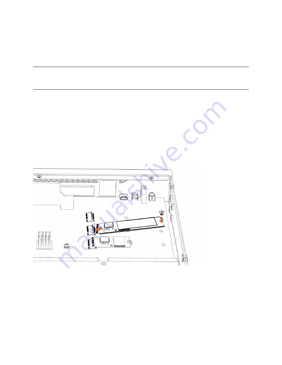
Replacing the SSDs in 1U CX 3080 appliances

The 1U CX 3080 appliance includes two internal SSD cards inside the appliance.

To replace the SSD in the 1U CX 3080 appliance

1. Remove the cover. For details, see 

“Removing the chassis cover” on page 10

.

2. Remove the locking screw on the SSD.

Figure 1-8. Removing the SSD locking screw 

3. Holding each side of the SSD, carefully pull the SSD from the pin connector.

Содержание SteelCentral AppResponse 2180

Страница 1: ...nce Guide SteelHead CX x80 and xx80 SteelHead Interceptor 9600 9800 SteelCentral AppResponse 2180 4180 8180 SteelCentral Flow Gateway 2280 SteelCentral NetProfiler 4280 4280 DP 4280 EXP Document revision September 16 2021 ...

Страница 2: ...trademarks of VMware Inc in the United States and in other countries This product includes Windows Azure Linux Agent developed by the Microsoft Corporation http www microsoft com Copyright 2017 Microsoft Corporation This product includes software developed by the University of California Berkeley and its contributors EMC and Comtech AHA Corporation This product is derived from the RSA Data Securit...

Страница 3: ...u begin 12 Replacing the HDDs in 1U CX 3080 appliances 13 Replacing the HDDs in 1U SteelCentral xx80 appliances 14 Replacing the SSDs in 1U CX 3080 appliances 15 Replacing power supply units 16 Replacing power supply units in 1U CX 3080 appliances 16 Replacing power supply units in 1U SteelCentral xx80 appliances 18 Replacing memory modules 18 Replacing fans 22 Determining the fan status on 1U CX ...

Страница 4: ...y with a DC power supply 51 Replacing memory modules 51 Replacing fans 52 Determining fan status 52 Replacing fans in 2U appliances 53 A Reference Appliance Specifications 55 CX 580 and CX 780 specifications 55 Port locations LEDs and buttons 55 Back panel ports and status lights 55 Technical specifications 57 Power consumption specifications 57 Environmental specifications 58 CX 3080 specificatio...

Страница 5: ...orts and status lights 71 B Reference Managing Appliances with BMC 73 Logging in to the BMC 74 Viewing sensor information 74 Viewing the field replaceable units 77 Viewing logs and reports 78 Viewing and modifying settings 80 Remotely controlling the appliance 80 Enabling image redirection 81 Controlling the power 81 Maintenance 82 Signing out of the BMC session 82 ...

Страница 6: ...6 Contents ...

Страница 7: ... bag that has been grounded or neutralized Store any appliance components in their protective packaging until you are ready to install them Don t touch the electronic components on the appliance Convention Meaning italics Within text new terms and emphasized words appear in italic typeface boldface Within text CLI commands CLI parameters and REST API properties appear in bold typeface Monospace Co...

Страница 8: ... titles or search for keywords and strings To access the Riverbed Knowledge Base log in to the Riverbed Support site at https support riverbed com Each software release includes release notes The release notes list new features known issues and fixed problems To obtain the most current version of the release notes go to the Software and Documentation section of the Riverbed Support site at https s...

Страница 9: ...ts for the appliance to function properly Installation of unapproved components will result in boot failure To order components contact Riverbed Support at https support riverbed com When you replace appliance components you must wear a grounded ESD antistatic strap to protect the hardware against electrostatic discharge Make sure that the strap makes skin contact prior to handling equipment Use t...

Страница 10: ...080 appliances on page 10 Removing the chassis cover on 1U SteelCentral xx80 appliances on page 11 Removing the chassis cover on 1U CX 3080 appliances This section describes how to remove and install the chassis cover on the 1U CX 3080 appliance To remove the chassis cover on 1U CX 3080 appliance 1 Power down the appliance and unplug all peripheral devices and the power cable 2 Facing the back of ...

Страница 11: ...igure 1 2 Figure 1 2 Removing the cover Removing the chassis cover on 1U SteelCentral xx80 appliances This section describes how to remove and install the chassis cover on the 1U SteelCentral xx80 appliances To remove the chassis cover on the 1U SteelCentral xx80 appliance 1 Power down the appliance and unplug all peripheral devices and the power cable ...

Страница 12: ...pliances on page 13 Replacing the HDDs in 1U SteelCentral xx80 appliances on page 14 Replacing the SSDs in 1U CX 3080 appliances on page 15 Before you begin When replacing a drive replace only one drive at a time You must use approved disk drives To order disk drives contact Riverbed Support at https support riverbed com If you need to replace an appliance you can t move the disks to preserve your...

Страница 13: ...eir carrier cases To replace the HDD in the 1U CX 3080 appliance 1 Remove the cover For details see Removing the chassis cover on page 10 2 To unlock the drive using a Phillips head screwdriver turn the screwhead on the drive 90 degrees to the left Figure 1 4 Unlocking the disk drive 3 Press the lock lever button The drive snaps open Figure 1 5 Removing the disk drive 4 Slide the faulty disk drive...

Страница 14: ...w disk drive In the web interface you can configure SteelHead appliances to send an email to the administrator when the disk drive has finished rebuilding Replacing the HDDs in 1U SteelCentral xx80 appliances The 1U SteelCentral xx80 appliances include four hot swappable HDDs Figure 1 7 1U SteelCentral xx80 disk drive numbers To replace the HDDs in the 1U SteelCentral xx80 appliance 1 Remove the b...

Страница 15: ...es approximately 3 to 4 hours depending on the system load to rebuild a new disk drive In the web interface you can configure SteelHead appliances to send an email to the administrator user when the disk drive has finished rebuilding Replacing the SSDs in 1U CX 3080 appliances The 1U CX 3080 appliance includes two internal SSD cards inside the appliance To replace the SSD in the 1U CX 3080 applian...

Страница 16: ...se sections Replacing power supply units in 1U CX 3080 appliances on page 16 Replacing power supply units in 1U SteelCentral xx80 appliances on page 18 Replacing power supply units in 1U CX 3080 appliances These appliances are equipped with replaceable hot swappable PS units The PS units are numbered Facing the rear of the appliance PS1 is on the right and PS0 is on the left Caution Use caution wh...

Страница 17: ...e 4 Slide the power supply unit out of the chassis Caution Put the defective power supply unit aside wait until it cools down before touching it 5 Press in and hold the orange latch see Figure 1 11 letter A and push the power supply into the chassis see Figure 1 11 letter B Figure 1 11 Inserting the power supply unit for the 1U CX 3080 appliance 6 Press the lock handle down see Figure 1 11 letter ...

Страница 18: ...y can become hot to the touch To replace power supply units in 1U SteelCentral xx80 appliances 1 Locate the defective power supply unit and remove the power cord 2 Press the latch and pull the power supply unit toward you 3 Slide the power supply unit out of the chassis Caution Put the defective power supply unit aside wait until it cools down before touching it 4 Press and hold the latch and push...

Страница 19: ...080 appliance is equipped with two DIMM slots slot 0 and slot 1 When replacing memory on the 1U CX 3080 appliance place the new memory module in the slot from which the faulty memory module was removed Figure 1 12 Memory module slot locations in the 1U CX 3080 appliance ...

Страница 20: ... 1U SteelCentral xx80 appliances To replace the memory modules in the 1U appliance 1 Power down the appliance 2 Remove the chassis cover 3 Press the locking clips outward to unlock them and gently pull the memory module out of the slot Figure 1 14 Releasing the locking clips Note Replacing the existing memory module with a module of a different size causes the appliance to fail You must use approv...

Страница 21: ...serted properly the memory slot locking levers lock automatically onto the indentations at the ends of the module Figure 1 15 Inserting the memory modules 5 Press the clips inward to lock the module in place Figure 1 16 Engaging the locking levers 6 Ensure that all clips are in the upright locked position 7 Replace the chassis cover ...

Страница 22: ...o the CLI For details see the Riverbed Command Line Interface Reference Manual 2 At the system prompt enter the show stats fan command The output and number of fans vary depending on your appliance On appliances where each fan has two rotors each rotor has a unique status entry Replacing the fans in 1U CX 3080 appliances This section describes how to replace the fan unit in 1U CX 3080 appliances T...

Страница 23: ...h the attached bracket into the fan slot Figure 1 18 Inserting the new fan 5 Replace the chassis cover For details see Removing the chassis cover on page 10 Note If the Intelligent Platform Management Interface IPMI alarm triggers when you open the chassis cover enter the clear hardware error log command in the CLI to clear the alarm For details see the Riverbed Command Line Interface Reference Ma...

Страница 24: ...quipped with six fans Figure 1 19 1U SteelCentral xx80 fan layout You must use approved fans To order fans contact Riverbed Support at https support riverbed com Important The fans aren t hot swappable you must power down the appliance before replacing the fans To replace the fan in the 1U SteelCentral xx80 appliance 1 Power down the appliance 2 Remove the chassis cover 3 Identify the faulty fan ...

Страница 25: ...Replacing 1U xx80 Components 25 Replacing fans 4 Unplug the fan cable located on the HDD backplane Figure 1 20 Unplugging the fan cable ...

Страница 26: ...26 Replacing 1U xx80 Components Replacing fans 5 To remove the fan pull straight up on each side of the fan The fan is removed including the attached flat metal fan bracket Figure 1 21 Removing the fan ...

Страница 27: ...g 1U xx80 Components 27 Replacing fans 6 Insert the new fan with the attached bracket into the fan slot Figure 1 22 Inserting the new fan 7 Plug the fan cable into the HDD backplane 8 Replace the chassis cover ...

Страница 28: ...28 Replacing 1U xx80 Components Replacing fans ...

Страница 29: ...ng fans on page 41 Appliances included in this chapter This chapter describes how to replace components in these 2U appliances SteelHead CX 5080 and CX 7080 Interceptor IC 9800 SteelCentral AppResponse 4180 and 8180 SteelCentral NetProfiler 4280 and 4280 EXP Required tools You need the following tools and equipment to replace appliance components You must use approved components for the appliance ...

Страница 30: ...ndle See Figure 2 1 letter A 3 Pull the left side of the front bezel toward you to release the latches on the left end from the rack handle Figure 2 1 displays a 2U appliance Figure 2 1 Removing the bezel 4 Pull the bezel away from the appliance See Figure 2 1 letter C Note The bezel that ships with your appliance might look different from the bezel in the figure To install the bezel 1 Insert the ...

Страница 31: ...top of the appliance and loosen the two screws See Figure 2 2 letter A on the back of the appliance Figure 2 2 Removing the chassis cover on the 2U xx80 and IC 9800 appliances 3 Place your thumbs on the recessed tabs See Figure 2 2 letter B and slide the cover straight back and up Note To install the chassis cover reverse the order of these steps Removing the riser brackets and air duct in 2U appl...

Страница 32: ...kets and air duct in 2U appliances 2 Remove the two screws on the top of the riser brackets and loosen the two screws on the back of the appliance Figure 2 3 Removing the screws from the riser brackets 3 Lift straight up to remove the riser brackets from the chassis ...

Страница 33: ...s on page 35 Before you begin When replacing a drive replace only one drive at a time You must use approved disk drives To order disk drives contact Riverbed Support at https support riverbed com If you need to replace an appliance you can t move the disks to preserve your data Each disk is encoded with machine level information and moving disks isn t supported When you replace disk drives you mus...

Страница 34: ...ble 3 5 inch HDDs When replacing a drive replace only one drive at a time You must use approved disk drives To order disk drives contact Riverbed Support at https support riverbed com Note When you replace disk drives you must wear a grounded ESD antistatic strap to protect the hardware against electrostatic discharge Make sure that the strap makes skin contact prior to handling equipment Caution ...

Страница 35: ...ly begins proper operation with the other disk drives You don t need to set up or configure the new disk drive For SteelCentral appliances see the user guide for the product if additional steps are necessary to run a self test Important For SteelHead appliances it takes approximately 3 to 4 hours depending on the system load to rebuild a new disk drive In the web interface you can configure SteelH...

Страница 36: ... Press the orange locking lever latch and pull the locking lever open Figure 2 7 Removing the 2 5 inch SSD on the rear of the 2U appliance 3 Insert the SSD drive into the chassis 4 Press the locking lever to secure the drive Figure 2 8 Securing the drive in the chassis ...

Страница 37: ...facing the rear of the appliance on the appliance PS0 is on the right and PS1 is on the left Caution Use caution when replacing the power supply units they can become hot to the touch To replace power supply units in the 2U appliance 1 Locate the defective power supply unit and remove the power cord 2 Press the latch and pull the power supply unit toward you Figure 2 9 Removing the power supply un...

Страница 38: ...atch and push the power supply into the chassis using the handle Figure 2 11 Inserting the power supply unit for 2U CX xx80 appliances 5 Plug the AC power cord into the new power supply unit Replacing memory modules in 2U appliances This section describes how to remove and replace memory modules DIMMs in the 2U CX xx80 and IC 9800 appliances Figure 2 12 Memory module slot locations in 2U appliance...

Страница 39: ...o replace a memory module in the 2U appliance 1 Power down the appliance 2 Remove the chassis cover For details see Removing the chassis cover on page 31 3 Remove the riser brackets and air duct For details see Removing the riser brackets and air duct in 2U appliances on page 31 4 If you are adding a new memory module to an empty slot make sure you remove the dummy DIMM before you add the new modu...

Страница 40: ...the ends of the module Figure 2 14 Inserting the memory modules 7 Press the clips inward to lock the module in place Figure 2 15 Ensuring the locking levers are locked 8 Ensure that all clips are in the upright locked position 9 Replace the riser brackets and air duct For details see Removing the riser brackets and air duct in 2U appliances on page 31 10 Replace the chassis cover 11 Replace the po...

Страница 41: ...o replacing fans Determining fan status on 2U CX xx80 and IC 9800 appliances This section describes how to determine the status of individual fans in the 2U CX xx80 and IC 9800 appliances To determine fan status on the appliance 1 Connect to the CLI For details see the Riverbed Command Line Interface Reference Manual 2 At the system prompt enter the show stats fan command The output and number of ...

Страница 42: ...ns in 2U CX xx80 and IC 9800 appliances The appliances are equipped with eight fans at the front of the chassis Figure 2 16 Fan layout You must use approved fans To order fans contact Riverbed Support at https support riverbed com To replace the fan in the 2U appliance 1 Power down the appliance 2 Remove the chassis cover 3 Identify the faulty fan ...

Страница 43: ...Components 43 Replacing fans 4 Disconnect the fan power cable from the backplane Figure 2 17 Disconnecting the fan power cable 5 Press the blue button and pull the fan straight up to remove it Figure 2 18 Removing the faulty fan ...

Страница 44: ...n slot 7 Plug in the fan power supply into the backplane 8 Replace the chassis cover Note If the IPMI alarm triggers when you open the chassis cover enter the clear hardware error log command in the CLI to clear the alarm For details see the Riverbed Command Line Interface Reference Manual ...

Страница 45: ... function properly Installation of unapproved components will result in boot failure To order components contact Riverbed Support at https support riverbed com An antistatic strap When you replace appliance components you must wear a grounded ESD antistatic strap to protect the hardware against electrostatic discharge Make sure that the strap makes skin contact prior to handling equipment Use the ...

Страница 46: ...lugging the SSD drive cables 2 Carefully push in the two latches on the air duct see Figure 3 2 letter A 3 Rotate the front edge of the air duct up to disengage the two tabs from the fan bulkhead see Figure 3 2 letter B Figure 3 2 Removing the air duct Replacing disk drives IC 9600 appliances are equipped with replaceable hot swappable 2 5 inch drives ...

Страница 47: ...sks isn t supported Caution Use caution when you remove or replace components they can become hot to the touch To replace the 2 5 inch disk drive 1 Remove the bezel See Removing the air duct on page 45 2 Identify the faulty disk drive The web interface identifies the faulty disk drive On a SteelHead the Alarm Status page in the Management Console identifies the faulty drive The disk drive LED is o...

Страница 48: ...gure 3 5 letter B Figure 3 5 Remove the disk drive 5 Remove the four screws securing the drive from the carrier and remove the failed drive Figure 3 6 letter C Figure 3 6 Removing the drive from the carrier 6 Insert the new drive in the carrier and secure using the four screws see Figure 3 7 letter D ...

Страница 49: ...etter E The disk drive LED lights blue when connected 9 Press in the disk drive handle to close see Figure 3 8 letter E Figure 3 8 Inserting the disk drive The new disk drive runs through a self test automatically The disk drive automatically begins proper operation with the other disk drives You don t need to set up or configure the new disk drive Replacing power supply units This section describ...

Страница 50: ...handle and pull the power supply unit toward you Figure 3 9 Removing the power supply unit Note Power supply 1 PS1 is on the right and power supply 2 PS2 is on the left 3 Pull the power supply unit out of the chassis Caution Put the defective power supply unit aside wait until it cools down before touching it 4 Slide in the new power supply unit until it clicks into place Figure 3 9 letter B Figur...

Страница 51: ...hten the screws around the wires Replacing memory modules This section describes how to remove and replace memory modules in the IC 9600 appliances Figure 3 11 shows memory module slot locations in IC 9600 appliances Figure 3 11 Memory module slot locations in 2U appliances When adding new memory to the 2U appliances add the memory in the blue slots first Once the blue slots are full populate the ...

Страница 52: ...nnector slot and securing 7 Press down on the memory module with your thumbs see Figure 3 12 letter C and B while pulling up on the ejectors with your index fingers see Figure 3 12 letter A and D to lock the module into the slot see Figure 3 12 letter E 8 Ensure that all ejector tabs are in the upright locked position 9 Replace the chassis cover 10 Replace the power cords and peripherals 11 Power ...

Страница 53: ...unique status entry The output and number of fans vary depending on your appliance Replacing fans in 2U appliances This section describes how to replace fans in the IC 9600 appliances These appliances are equipped with five fans at the front of the chassis Important You must use approved fans To order fans contact Riverbed Support at https support riverbed com To replace the fans in the 2U applian...

Страница 54: ... Removing the fan in 2U appliances 5 Insert the replacement fan 6 Replace the chassis cover Note If the IPMI alarm triggers when you open the chassis cover enter the clear hardware error log command in the CLI to clear the alarm For details see the Riverbed Command Line Interface Reference Manual ...

Страница 55: ... CX 7080 specifications on page 62 Interceptor 9800 specifications on page 66 Interceptor 9600 specifications on page 68 CX 580 and CX 780 specifications This section describes the appliance specifications for SteelHead CX 580 and CX 780 Port locations LEDs and buttons This figure illustrates the front of the appliance including LEDs and buttons Figure A 1 CX 580 and CX 780 front panel Back panel ...

Страница 56: ...off LED 4 Not used default is off Reset button Restores system to factory defaults Console port RJ45 port USB ports v3 0 1 USB Type A port 1 USB Type C port Port 1 PRI Left LED Link Bypass Link On Solid green Activity Blinks green Right LED Speed 10 Mbps data rate Off 100 Mbps data rate Green 1000 Mbps data rate Amber Port 2 AUX Left LED Link Bypass Link On Solid green Activity Blinks green Right ...

Страница 57: ...econd power supply has power Amber Power on with warning 1 Hz blinks amber indicates high temperature high power high current or slow fan Specification CX 580 Desktop CX 780 Desktop Power Watt typical 37 W 60 W BTU 128 BTU 205 BTU RAM 16 GB 16 GB HDD 1 x 1 TB 1 x 1TB SSD 1 x 32 GB for boot 1 x 32 GB for boot Data store 200 GB 200 GB Dimensions LxWxH 12 25 x 13 75 x 1 73 in 311 15 x 349 25 x 44 mm ...

Страница 58: ...SU type 2 x 550 W AC input 120 V 240 V Max watts 46 8 W 33 2 W Max amps 0 486 A 0 22 A Power factor 97 71 W VA 94 8 W VA Max volt ampere 47 89 VA 35 02 VA Typical watts 37 44 W 26 56 W BTU typical 127 67 BTU 90 56 BTU Specification CX 580 Desktop CX 780 Desktop Operating acoustic 45 dBA sound pressure typical 45 dBA sound pressure typical Temperature operating 0 to 45 C 32 to 113 F 0 to 45 C 32 to...

Страница 59: ...s the system state LED 1 Yellow LED 2 Yellow System State Critical LED 1 Yellow LED 2 Green System State Degraded LED 1 Green LED 2 Green System State Healthy LED 3 Not used default is off LED 4 Not used default is off Reset Button Press to restore factory defaults Console port RJ45 port USB Ports v3 0 1 USB Type A port 1 USB Type C port Port 1 PRI Primary port Left LED Link Green Activity Blinks ...

Страница 60: ...ED 10 Mbps data rate No light with link on left LED 100 Mbps data rate Green 1000 Mbps 1 Gbps Yellow Ports 7 8 on board Not used LED button Description HDDs Activity LED upper light Activity Blinks green drive present with activity Status LED lower light Failed Disk Solid amber Power Supply LEDs Power on and healthy Green Standby 1 Hz blinks green Power Off Off Unplugged or power lost but second p...

Страница 61: ... 17 24 x1 73 in 387 35 x 483 x 44 mm Weight without packaging 27 lb 12 25 kg Power Typical 70 W BTU 242 Voltage 100 240 V PSU 2 x hot swappable redundant 550 W W 100 240 VAC 7 1 3 4 A 47 63 Hz PCIe slots 1 FHFL full height full length Bypass ports maximum 4 on board 8 with add on card System CX 3080 PSU type 2 x 550 W AC input 120 V 240 V Max watts 88 7 W 73 8 W Max amps 0 9144 A 0 488 A Power fac...

Страница 62: ...20 to 80 noncondensing Operating 10 to 95 noncondensing Storage Reference LED button Description 1 Power On Off Button and Integrated LED On Green System is turned on Sleep State Green System is in S1 or S3 sleep state Off No light Power is off 2 IPMI Warning LED The IPMI Warning LED shows the current health of the server system Normal Green No failures Degraded Warning Amber Indicates fan failure...

Страница 63: ...ample for slot 4 the interface ports would be LAN4_0 WAN4_0 LAN4_1 WAN4_1 4 Reset Button Press to reboot the appliance 5 System ID Button Press the system ID button when the system AC alternating current is on The system ID LED indicates the system is identified with a blue light Users from a remote site can activate the ID LED by inputting commands in IPMI For details contact Riverbed Support 6 7...

Страница 64: ...ort at https support riverbed com Primary and AUX Port LEDs Left LED Link Green Activity Blinks green No Link Off Right LED 10 Mbps Off 100 Mbps Green 1000 Mbps Amber Four Port 1 GbE Copper Bypass Card LEDs preinstalled Link Activity LED Link Green Activity Blinks green Speed Bypass Disconnect LED 1000 Mbps Yellow 100 Mbps Green 10 Mbps Off Bypass Blinks green Disconnect Blinks yellow Power Supply...

Страница 65: ...1 lb 23 kg Voltage 100 127 V 200 to 240 V 100 127 V 200 240 V PSU 2 x 770 W 100 127 VAC 10 A 50 60 Hz 200 240 VAC 5 A 50 60 Hz 2 x 770 W 100 127 VAC 10 A 50 60 Hz 200 240 VAC 5 A 50 60 Hz PCI slots 6 6 Included bypass ports max ports 4 20 4 20 System CX 5080 CX 7080 CX 7080 Configuration B010 B010 B020 B030 PSU type 2 x 770 W 2 x 770 W 2 x 770 W AC input 120 V 230 V 120 V 230 V 120 V 230 V Max amp...

Страница 66: ...he 2U Interceptor IC 9800 2U appliances Port locations LEDs and buttons This figure illustrates the front of the appliance including LEDs and buttons Figure A 7 IC 9800 front panel with LEDs and buttons Specification CX 5080 CX 7080 Operating acoustic 56 dB typical 56 dB typical Temperature operating 32 to 104 F 0 to 40 C 32 to 104 F 0 to 40 C Temperature storage 40 to 140 F 40 to 60 C 40 to 140 F...

Страница 67: ...re over voltage or power supply failure Critical Blinking Amber and Green Indicates a problem that needs attention such as optimization service down no license or in_path is not enabled for optimization service 3 ID LED On Blue System identified remotely on the server Off Off System not identified 4 Reset Button Press to reboot the appliance 5 System ID Button Press the system ID button when the s...

Страница 68: ...t Users from a remote site can activate the ID LED by inputting commands in IPMI For details contact Riverbed Support at https support riverbed com Primary and AUX Port LEDs Left LED Link Green Activity Blinks green No Link Off Right LED 10 Mbps Off 100 Mbps Green 1000 Mbps Amber Four Port 1 GbE Copper Bypass Card LEDs preinstalled Link Activity LED Link Green Activity Blinks green Speed Bypass Di...

Страница 69: ...igent Platform Management Interface IPMI ipmitool chassis identify command which causes the LED to blink for 15 seconds A duplicate System ID LED is on the back of the appliance to the left of the video port 2 NMI Button Pressing the NMI button puts the appliance in a halt state and issues a nonmaskable interrupt NMI This helps when performing diagnostics for a given issue where a memory download ...

Страница 70: ...range RAID Rebuild Blinks orange LEDs on Primary and AUX Ports Left LED Link Green Activity Blinks green Right LED 10 Mbps data rate No light with link on left LED 100 Mbps data rate Green 1000 Mbps data rate Yellow LEDs on Default Four Port Copper Bypass Card Link Activity LED Link Green Activity Blinks green Speed Bypass Disconnect LED 1000 Mbps Yellow 100 Mbps Green 10 Mbps Off Bypass Blinks gr...

Страница 71: ...e including the ports Figure A 10 IC 9600 back panel Note By default the SteelHead Interceptor 9600 ships with a bypass card in slot 1 The default interface names are LAN1_0 WAN1_0 LAN1_1 and WAN1_1 This appliance doesn t have an inpath0_0 interface as found on earlier appliances and by default the SteelHead Interceptor 9600 uses inpath1_0 and inpath1_1 ...

Страница 72: ...72 Reference Appliance Specifications Interceptor 9600 specifications ...

Страница 73: ...nd CX 3080 appliances use the primary port as the BMC port for communication The AUX port does not support BMC communication on these appliances Important The SteelHead CX 5080 CX 7080 and IC 9800 appliances use the RJ45 port located above the USB ports as the BMC port for communication The PRI AUX ports do not support BMC communication on these appliances This appendix provides an overview of the...

Страница 74: ...n of the primary port For 2U CX 5080 CX 7080 and IC 9800 appliances connect to the BMC RJ45 port see CX 5080 and CX 7080 back panel on page 63 2 In a web browser enter the IP address To display the BMC IP address for a SteelHead from the command line use the show remote ip command 3 If the connection isn t trusted possibly using a self signed certificate you are prompted to add and confirm a secur...

Страница 75: ...pliances with BMC 75 Viewing sensor information The Sensor Reading page refreshes automatically with live data retrieved from the database There might be some delay in retrieving the live data Figure B 2 Sensor Reading page ...

Страница 76: ...ensor name to display the Sensor detail page This page displays information events and thresholds The graph is a live representation of the sensor readings Figure B 3 Sensor details page 2 Mouse over the graph point to view the sensor information 3 Scroll to Sensor Events to view all the event entries for this sensor in a reverse chronological order ...

Страница 77: ...ption is disabled Figure B 4 Changing sensor thresholds 5 Enter the desired threshold values and click Save Viewing the field replaceable units The Field Replaceable Units FRU Information page displays Available FRU devices Select the FRU ID to display detailed information Chassis information Displays the format version type part number serial number and add ons Board information Displays the form...

Страница 78: ...ports Product Information Displays format version language manufacturer name version serial number asset tag file ID and add ons Figure B 5 FRU Information page Viewing logs and reports Choose Logs Reports report name to view IPMI logs event logs and system logs ...

Страница 79: ...f events by date You can also select between BMC or Client Time zone Click a record to see the details of that entry Clearing event logs deletes all existing records for all sensors Figure B 6 IPMI Event Log page System logs Displays system logs of system events for this device if the options have been configured To configure system events choose Settings Log Settings Advanced Log Settings Filteri...

Страница 80: ... settings Network Settings Modify network IP settings network link configuration DNS configuration and sideband interface settings PAM Order Settings Modify the PAM Pluggable Authentication Modules order for user authentication into the BMC Platform Event Filter Modify event filters alert policies and LAN destinations Services Modify web KVM CD media FD media and HD media settings SMTP Settings Mo...

Страница 81: ...ngs To start redirection or clear an image you must have administrator privileges The table shows remote images available to the BMC You can start redirection or clear the images from here Only Single image can be configured for each image type depending on your configuration To start and stop image redirection 1 Click Play to redirect the selected image 2 Click Stop to stop the remote image redir...

Страница 82: ...ies to reset the BMC from 1 to 5 set the number of retries from 1 to 5 to recover a firmware image during the recovery process set the address of the server where the firmware image will be stored set the image name Firmware Image Location Set the protocol to be used to transfer the firmware image onto the BMC Web upload during flash or TFTP server Firmware Information Displays the firmware image ...

Отзывы: