background image

4 Transporting the machine 


Ritta l electrical crimping machine R8 E 

We reserve the right to make technical m odifications. 

11 

EN 

4


Transporting the machine 

Always use the complete original packaging for transport. 


Note: 
The machine with all its accessories must be sent for service and re-
pair work. 


Caution! 
Force can cause damage to the machine. 


Transport the machine properly. 


Caution! 
There is a risk of injury, in particular to feet, should the machine fall. 


Wear safety shoes when transporting the machine. 

5


Setting up the machine 


Read the operating instructions carefully before commissioning the machine. 


Deploy the machine only in a dry environment. 

5.1


Operating tools 


Tools 

Included in the scope of supply 

Allen key size 4 


Allen key size 2.5 


Tweezers 


5.2


Machine connection 


Caution! 
The electrical data shown on the rating plate must match that of the power grid.  


Otherwise, damage can occur to the machine. 


Connect the mains cable to the mains plug (see fig. 3, item 3) of the machine and 
to the power supply. 


Switch on the electrical crimping machine R8 E at the power switch (see fig. 3
item 1). 

Содержание R8 E

Страница 1: ...AS 4050 454 Electrical crimping machine R8 E Operating instructions ...

Страница 2: ... the machine 11 5 1 Operating tools 11 5 2 Machine connection 11 5 3 Inserting the beltroll 12 5 4 Cross section setting 13 5 4 1 Die size setting 14 5 4 2 Insulation stripping stage setting 15 5 5 Replacing the belt roll 15 5 6 Conductor insertion conductor cutting 15 6 Menu 16 6 1 Joggingoperation 16 6 2 Counters 17 6 2 1 Reset daily quantity counter 17 6 2 2 Service counter 17 6 3 Fillinglevel ...

Страница 3: ...ht to make technical modifications 3 EN 8 4 Error messages 25 8 5 Removingthe wire end ferrule 26 9 Machine decommissioning and disposal 26 9 1 Machine decommissioning 26 9 2 Machine disposal 26 10 Electrical connection diagram 27 11 Spare parts list and accessories 28 ...

Страница 4: ...ionto the notices specified Caution Propertydamage Noticeswith the signal word attention warnyou aboutdangerswhichcould resultin damage to property Situation related warningsmay contain the followingwarningsymbols Symbol Meaning Warning dangerous electrical voltage Warning injury to hands due to sharp blades Work may only be performed by a qualified electrician Only perform work with personal prot...

Страница 5: ...ntation Rittal electrical crimping machine R8 E We reserve the right to make technical modifications 5 EN Bulletpointsare indicatedwith dashes Operatinginstructionsin other languagescan be foundon our website Click here ...

Страница 6: ...ultbecause of the precedingmeasures Use only original sparepartsand accessoriesauthorised by the manufacturer The use of other partsvoidsthe liability for any damage also consequentialdamages that resultsfromthe use of other partsor non authorisedaccessories 2 2 Not permitted Removingnotification or warningsigns Openingthe machineduringoperation Usingthe machine with obviousdefectsor damage 2 3 Ma...

Страница 7: ...otectiveconductor green yellowinsulatingsheathonly in Germany isused for these protective measures 2 8 Residualrisks Even when all safety and warningnotesareobserved residual risksremain forthe machine operation The machine isstate of the artand builtaccordingto recognisedsafety regula tions Nevertheless hazardsforusersor third partiescan resultwhen operating the machine The machine may be usedonl...

Страница 8: ...shavedifferentauthorisations 2 11 1 Operator Requirements Literacy skills Technical knowledge Instructed trained Knowledge Machine function Intended use of the machine Machine safety devices 2 11 2 Technician Requirements Rittal servicetechnician Work steps Target group Operator Technician Transporting X X Mounting X Dismantling X Setup X X Operation X X Cleaning X X Maintenance X X Repairs X 2 12...

Страница 9: ... description Rittal electrical crimping machine R8 E We reserve the right to make technical modifications 9 EN 3 Device description 3 1 Overview Fig 1 Front view Fig 2 Connectioncircuit board 1 2 3 4 5 6 7 8 9 ...

Страница 10: ...form Trapezoidal Drive Electric motor Voltage 100 240 V Frequency 50 60 Hz Power consumption 100 VA Fuse mains filter module 2 x T2AH250V Degree ofprotection IP 20 Protection class I PE conductor Cycle time 1 8 s Continuous sound pressure level 70 dB A Dimensions W x D x H 288 mm x 349 mm x 230 mm Weight 16 kg Operating environment Storage transport temperature 25 C to 55 C short term 70 C Ambient...

Страница 11: ...d themachinefall Wear safety shoeswhentransportingthe machine 5 Setting up the machine Read the operatinginstructionscarefully beforecommissioningthe machine Deploy the machine onlyin adry environment 5 1 Operating tools Tools Included in the scope ofsupply Allen key size 4 Allen key size 2 5 Tweezers 5 2 Machine connection Caution The electrical datashown on the ratingplate mustmatch thatof the p...

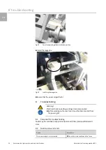
Страница 12: ...serting thebelt roll Place the beltroll seefig 4 item1 so thatclockwiseunrollingispossible Open the twistlock see fig 4 item2 and swivel theflap to the side The transportpin mustbe atthe bottom Fig 4 Inserting thebeltroll Push the wire end ferrulebeltinto the magazine until thelowermostferrule latches Butnot further becauseotherwiseamalfunction can occur Check thisby applying slighttensionto the b...

Страница 13: ...ons 13 EN Fig 5 Feeding inthewire end ferrules Close the flap viathe twistlock Roll up the loose wire endferrulebelt Fig 6 End position 5 4 Cross sectionsetting Fig 7 Display menu display Key 1 Die size 2 Insulation stripping stage 3 Conductor cross section 4 Day quantity counter 5 Initial position symbol 2 1 3 5 4 ...

Страница 14: ... I II III 99 Tab 1 Setting values 5 4 1 Die size setting Open the twistlock Swivel the flap to the side Caution There isrisk of fingerinjuriesby thefixedferrule separatingblade Do nottouch the blade whenthe drumisturned Pressthe drumbackwards seefig 8 item1 and turn seefig 8 item2 to the desired diesize Release the drumuntil itlatches The currentnestisdisplayed with the bars see fig 8 item3 Check ...

Страница 15: ...ion stripping stage setting 5 5 Replacing the belt roll Open the twistlock Swivel the flap to the side Pressthe transportpin upwardscompletely see fig 10 item1 and removethe wire end ferrulebelt seefig 10 item2 fromthe magazine Continue in accordancewith section5 3 Insertingthe beltroll Fig 10 Replacing the belt roll 5 6 Conductor insertion conductor cutting Note The cable mustbe cutstraightand mu...

Страница 16: ...rippingstages1 to 15 mustbe set Switch off the machine Open the flap Remove the belt Close the flap Keep the display pressed Switch on the machine machinein joggingoperation The display switchesto the Joggingoperationinitial position display Traverse backwards seefig 11 item1 or forwards seefig 11 item2 in jog gingoperation usingthearrowkeys Traverse the machinemanuallyuntil the initial position s...

Страница 17: ...sentto the manufacturer 6 3 Filling level monitoring The fillinglevel monitoringcheckswhetherthe startswitch hasbeenpressed suffi ciently long Thisfunction isactive asstandard Deactivate activatethe function Setinsulation strippingstage 99 Pressthe touch display for3 seconds The currentstatusof the fillinglevel monitoringisdisplayed X On O Off Tap the touch display briefly to changethe status Pres...

Страница 18: ...Maintenancework may be performedonly by specially trainedand instructed per sonnel 7 2 Maintenancenotes Note Never cleanthe machineinteriorwith compressed air Do notuse spray oil or spray grease If possible use siliconeor PTFEoils Teflon oil e g Divinol GWAISO 46 Use lubricatinggreasessuitablefor rollerbearingsand slidingsur faces The display and the touch screenare madeof plastic and mustnot come...

Страница 19: ... 7 4 Maintenanceschedule 7 4 1 Daily maintenance Component Activity Machine Empty the refuse drawer Emptyingthe refuse drawer Observethe insertion position of the refusedrawer Fig 14 Refuse drawer 7 4 2 Monthly maintenance Open the flap Oil the support seefig 15 item1 and bearingassembly see fig 15 item2 of the crimpingdrum ...

Страница 20: ...g 15 Oiling the crimping drum 7 4 3 6 monthly maintenance Dismantle the housing Oil the gap between the settingwheel and the insulationstrippingstage To do this place the machineat45 Allowlubricatingoil to flowinto the gap see fig 16 item1 betweenthe setting wheel and the cover Fig 16 Oiling insulation stripping stage setting ...

Страница 21: ...ve the right to make technical modifications 21 EN Component Activity Shafts Grease all marked shafts and guides of the machine Fig 17 Shafts Component Activity Cams Apply the above mentioned grease with a brush to the grooves for all marked components Fig 18 Side view right ...

Страница 22: ...tchon the machine The machine travelsto the blade replacementposition seedisplay Switch off the machine Open the flap Remove the screws see fig 19 item1 Replace the insulation strippingblade see fig 19 item2 Insertthe insulation strippingblade in the blade holder until thelimitstop Close the flap Switch on the machine seedisplay Pressthe display for3 seconds The machine travelsautomatically to the...

Страница 23: ...ize 4 see fig 20 item1 Remove the magazine atthe top see fig 20 item2 Fig 20 Magazine Remove the two screwswith an Allen key size 2 5 see fig 21 item3 Remove the separatingblade cover see fig 21 item4 Replace the ferruleseparatingblade see fig 21 item5 Fig 21 Replacing the ferruleseparating blade The installation isperformedin the reverseorder Observethe installationpositionof the ferruleseparatin...

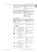
Страница 24: ...azine Ensure thatthe upperedgeisflush 8 Troubleshooting Warning Electrical shock causedby workingon livecomponents Before workingon the machine it mustbe disconnected from the power grid 8 1 Personnel for troubleshooting Faultsmay the rectified onlyby trained personnel fitters and qualified electri cians 8 2 Machine does not start Cause Correction The power supply is interrupted Check the mains ca...

Страница 25: ...splay Cause Correction The flap is open Close the flap Ferrule not removed after work cycle Remove the ferrule see section 8 5 Removing the wire end fer rule Triggering mechanism pressed too briefly ma chine does not start Press the touch display once briefly Triggering mechanism pressed too briefly ma chine starts Press the touch display once briefly Check the crimp quality Stop switch fault The ...

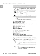
Страница 26: ...h for missingwireend ferrule If required removethe transportunit seesection7 6 Replacingferruleseparat ingblade Remove the wireend ferrule If required reinstall the transportunit Close the frontflap Tap the touch display briefly 9 Machine decommissioning and disposal 9 1 Machine decommissioning Switch off the machine Withdrawthe mainsplug Pack the machine in the originalpackaging The machine isnow...

Страница 27: ...10 Electricalconnectiondiagram Rittal electrical crimping machine R8 E We reserve the right to make technical modifications 27 EN 10 Electrical connection diagram ...

Страница 28: ...ies No Designation Model no 2 AS wire end ferrules belt 0 5 mm 8 mm long 4050 746 3 AS wire end ferrules belt 0 75 mm 8 mm long 4050 747 4 AS wire end ferrules belt 1 00 mm 8 mm long 4050 748 3 AS wire end ferrules belt 1 5 mm 8 mm long 4050 749 3 AS wire end ferrules belt 2 5 mm 8 mm long 4050 750 Note In the eventof an order specify the serial numberof the machine ...

Страница 29: ...ld here www rittal com contact RITTAL GmbH Co KG Postfach 1662 D 35726 Herborn Phone 49 0 2772 505 0 Fax 49 0 2772 505 2319 E mail info rittal de www rittal com 08 2021 D 0100 00000026 01 EN Enclosures Power Distribution Climate Control IT Infrastructure Software Services ...

Отзывы: