background image

www.ritm.ru

69 of 173

Operating Manual. Voyager 2N

Input terminals

Discrete inputs

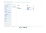
Inputs 1 and 2 (Fig. 22) are discrete. You can either turn them off or set 

as “discrete”.

After the input type has been selected, you can specify its designation:

•  Mechanism;
•  Ignition (only Input 1);
•  Panic button.

Then, the signal polarity at input has to be selected as either negative 

or positive, and the duration of the control signal, below which any data 

would be ignored.

Содержание Voyager 2N

Страница 1: ...St Petersburg 2017 GPS GLONASS tracker Voyager 2N Operating Manual Rev 1 3 ...

Страница 2: ... Voyager 2N ARI 14 Voyager 2N ATOL 16 Voyager 2N LIGHT 18 Voyager 2N LIGHT RS 485 20 Indication 22 GPS GLONASS reception indicator 22 SIM card reception indicators 23 Power indicator 23 Delivery Package 23 Intended Use 24 Operating Limits 24 Unpacking Tracker 24 Visual Inspection 24 Getting Ready for Operation 25 Monitoring Server Data 25 GSM Package Selection 25 SIM card Insertion 26 Battery Inst...

Страница 3: ...ls 37 Date and Time 39 Operation Modes 41 SMS messages 46 Track 50 A GPS 53 Sensors 55 Counters 67 Input terminals 69 Output terminals 73 Indication 75 Communication channels 77 Coordinate Receipt Servers 79 GPRS Parameters 83 Wi Fi parameters 86 EGTS Parameters 94 EGTS statistics 97 Dispatch 99 Message Terminal 101 History Structure 110 History 112 Engineering Numbers 114 Autoinformer 116 CAN 118...

Страница 4: ... 144 Frequency Analog Fuel Gauge Unit Connection 147 Connection to vehicle CAN bus 149 Connection of IRMA MATRIX traffic sensors 150 Connection of dispatch unit 152 Temperature Sensor Connection 154 Touch Memory Reader Connection 155 Tracker Test Procedure 156 Maintenance 158 Safety Precautions 159 Transportation and Storage 160 Manufacturer s Warranties 161 Disposal Note 162 SMS commands 163 JSON...

Страница 5: ...n the vehicle 1 This manual contains data on the design principle of operation tracker properties its parts and guidelines for proper and safe operation of tracker intended use maintenance storage and transportation This operating manual provides necessary information for preparatory training and further use of tracker This manual covers the following tracker versions 1 Voyager 2N 2 Voyager 2N 3G ...

Страница 6: ...he monitoring software Transfer of data to the coordinate receipt server is done via a GSM cellular communication channel The tracker may operate only provided that an intact activated SIM card is used that has not been locked by an MNO and has an activated package of necessary services GPRS CSD roaming Independent power supply from a battery3 allows the tracker to be used as a portable device for...

Страница 7: ...nd receiving data over IEE 802 11 Wi Fi wireless networks enabling it to serve as an access point for driver identification or as a client capable of connecting to wireless networks for further data transfer and configuration setup via server Voyager 2N ATOL is a version completed in a special enclosure enabling receipt of data from ATOL Drive5 tachographs Voyager 2N LIGHT is a cheaper version of ...

Страница 8: ...Connection of digital fuel gauge units Yes via RS 232 and RS 485 interfaces Connection of Touch Memory reader Connection of audio actuation device Yes in ARI Version Connection of dispatch unit Universal inputs discrete frequency analog counter 2 Discrete inputs 2 Outputs 1 A 2 External indicators GPS GLONASS Reception SIM1 Reception SIM2 Reception External Power Built in motion sensor Non volatil...

Страница 9: ...S GSM antenna Built in GPS GLONASS antenna Built in Number of SIM cards pcs 1 Type of SIM cards micro SIM PC connection over USB Discrete input 1 Connection of digital fuel gauge units Yes over RS 485 interface for LIGHT RS 485 Version External indicators Test Built in motion sensor Non volatile memory No of entries 29 000 External supply V 10 36 Tracker energy consumption A 0 02 0 15 depending on...

Страница 10: ...www ritm ru 10 of 173 Operating Manual Voyager 2N Design The tracker is made in a plastic enclosure Different tracker versions have their unique design features Voyager 2N ...

Страница 11: ...ion Tamper button When the battery compartment cover is opened device operating indicators turn on When the cover is closed the indicators are turn off USB connector For configuration cable connection 20 pin connector For connection of power supply and peripherals ...

Страница 12: ...www ritm ru 12 of 173 Operating Manual Voyager 2N Voyager 2N Wi Fi ...

Страница 13: ...compartment cover is opened device operating indicators turn on When the cover is closed the indicators turn off USB connector For configuration cable connection 20 pin connector For connection of power supply and peripherals SIM card 1 box SIM card 2 box Battery installation location Tamper button ...

Страница 14: ...yager 2N ARI USB connector SIM card 1 operation indicator SIM card 2 operation indicator Power indicator GSM antenna connector 20 pin connector Connector for GPS GLONASS antenna Connector for audio actuation device GPS GLONASS signal reception indicator ...

Страница 15: ...hen the cover is closed the indicators are turn off USB connector For configuration cable connection Connector for audio actuation device For connection of external speaker or amplifier Required for IVR 20 pin connector For connection of power supply and peripherals microSD memory card box SIM card 1 box Tamper button SIM card 2 box Battery installation location ...

Страница 16: ...73 Operating Manual Voyager 2N Voyager 2N ATOL Device status indicators SIM card connector GSM antenna connector 20 pin connector Connector for GPS GLONASS antenna microSD connector Tachograph connector RITM Voyager 2N T ...

Страница 17: ...configuration cable connection 20 pin connector For connection of power supply and peripherals Tachograph connector Connector for ATOL Drive5 tachograph GPS GLONASS signal reception indicator SIM card 1 operation indicator SIM card 2 operation indicator Power indicator RITM Voyager 2N T ...

Страница 18: ...www ritm ru 18 of 173 Operating Manual Voyager 2N Voyager 2N LIGHT USB connector Test indicator 20 pin connector ...

Страница 19: ...ing the tracker up from the sleep mode turning on the GPS receiver and the GSM modem as well as for switching on off the GPS receiver operation indicators USB connector For configuration cable connection 20 pin connector For connection of power supply and peripherals Test button SIM card box ...

Страница 20: ...www ritm ru 20 of 173 Operating Manual Voyager 2N Voyager 2N LIGHT RS 485 USB connector Test indicator 20 pin connector ...

Страница 21: ...he sleep mode turning on the GPS receiver and the GSM modem as well as for switching on off the GPS receiver operation indicators USB connector For configuration cable connection 20 pin connector For connection of power supply discrete input devices with RS 485 interface SIM card box Battery connector Test indicator ...

Страница 22: ... work mode all indicators blink at the same frequency i By default all indicators work only when the battery compartment cover is open and for no longer than 30 minutes To ensure continuous work of indicators choose the Permanent mode in Section Indication After the tracker has entered its work mode the indicators act as described below GPS GLONASS reception indicator Indicator state Value Off GPS...

Страница 23: ...5 include one Test indicator The indicator is switched on by pressing the Test button and operates for 30 minutes If satellites are not determined the indicator blinks frequently If satellites are determined the indicator blinks rarely The indicator may be turned off by pressing the button again To operate the indicator does not require connection to the vehicle s on board mains works from a built...

Страница 24: ... to the data sheet Visual Inspection After unpacking the tracker check the following The condition and completeness of the operation documentation Absence of mechanical damage of the tracker connector cable and integrity of protective and decorative coatings If the check reveals any defects or lack of any components fill out a report which should include the manufacture and commissioning dates and...

Страница 25: ... server port i eu ritm ru is used by default GSM Package Selection Choosing a package for a SIM card to be installed in the device please verify the availability of the following channels in the package s list of services GPRS This channel is used for transmission of navigation data to monitoring software and setup via cloud based software CSD This channel is used for configuration Voice Voice cha...

Страница 26: ...y feature check availability of data links that are to be used CSD GPRS and check if the balance is positive Open the cover on the tracker enclosure and insert SIM cards into the holders Battery Installation Install a battery to the tracker battery compartment6 The battery will automatically charge whenever the tracker is connected to an external power source The voltage value threshold above whic...

Страница 27: ...e applications Remote configuration via TCP IP To connect use a GSM GPRS channel and cloud based configuration software GEO RITM and RITM Link i To use ritm conf configuration software download it from the Ritm s official website To use Ritm Configure application install it in the Chrome Web Store To connect using a Micro USB cable install the necessary drivers To connect via a digital CSD channel...

Страница 28: ...e tracker on the vehicle Tracker Operation After the tracker powers on all of its indicators turn on for a while then the tracker goes into the previously configured operation mode All indicators go off when the cover is closed tamper button pressed To determine the location using a GPS GLONASS signal the tracker has to be in the place under the sky In buildings underground parkings subway and oth...

Страница 29: ...n operator in the dispatch center via a GSM voice channel Universal inputs Input type discrete analog or frequency is set up in the configuration software A discrete input features a configurable polarity and can be used for connecting a security system monitored mechanism or a panic button to the tracker The analog and frequency inputs can be connected to fuel consumption and level meters IRMA MA...

Страница 30: ...on with the tracker over a USB cable you will need to install an appropriate driver This driver can be downloaded from the official manufacturer s website in the Mobile Object Monitoring Systems section Voyager 2N tab To verify the availability and working condition of the driver connect a cable to your PC and open the Device Manager section Ports subsection Fig 1 This subsection will show the nam...

Страница 31: ...Figure 1 Driver Check ...

Страница 32: ...for protection from non authorized connection set the Master Code flag and enter it in a corresponding field i By default the Master Code is not used for connection Click on the Connect hyperlink and begin the tracker configuration procedure Configuration over CSD For a remote connection to the tracker over a CSD channel Fig 3 using a GSM modem open the Connection Wizard and specify the following ...

Страница 33: ...ce CSD is enabled and the balance of the SIM card installed in the device is sufficient The remote configuration via CSD is only possible from the engineering phone numbers Configuration via GEO RITM To access the configuration software via GEO RITM cloud based software open the object card s tab Equipment Fig 4 Below the tracker picture click Setup a device ...

Страница 34: ...ation via GEO RITM Configuration via RITM Link To access the configuration software via RITM Link cloud based software open the Devices section Fig 5 Use the pop up menu to open the configuration software by clicking the Setup line Figure 5 Device configuration via RITM Link ...

Страница 35: ...g areas Fig 7 1 Configuration software sections 2 Settings area 3 Configuration software versions 4 Details on Time of connection to device Current status and connection parameters Version of device firmware The tracker configuration procedure is composed of switching between different sections of the configuration software and setting the required parameters i If any firmware updates are availabl...

Страница 36: ...Operating Manual Voyager 2N Figure 7 Configuration software s Main page ...

Страница 37: ...send the SMS messages about alarm events from the tracker The SMS sending parameters as well as transmitted alarm events are configured in the SMS messages section 11 IMEI is required for adding the tracker to the monitoring software GEO RITM IMEI is also listed in the data sheet 12 The Tracking mode allows receiving object data more often than the Normal mode An example of situation where trackin...

Страница 38: ...Operating Manual Voyager 2N Figure 8 Device Details section ...

Страница 39: ...e date and time settings Each time coordinates are received from a satellite the tracker automatically adjusts the date and time settings However when the tracker is out of coverage of a strong satellite signal the date and time have to be set manually To do this use the Synchronise with this computer now hyperlink Synchronise with this computer now Immediate synchronization of the time with the P...

Страница 40: ...Operating Manual Voyager 2N Figure 9 Date and Time section ...

Страница 41: ... the three most typical operation modes of the tracker which have all the conditions previously set or a custom mode which allows fine tuning of all parameters Online mode This mode enables monitoring of an object in a continuous and uninterrupted way The tracker is always on constantly seeking and determining coordinates and sending data to the server over a GSM network This mode is characterized...

Страница 42: ...ensor for settings see Section Sensors To ensure proper operation of the motion sensor we recommend using data listed in Chapter Tracker Installation on Vehicle Online at motion The most energy saving mode The navigation receiver works only when both the vehicle is moving and the engine is running The tracker submits data to the server and receives commands over a GSM network only when the vehicle...

Страница 43: ...Operating Manual Voyager 2N Figure 10 Operation Modes section ...

Страница 44: ... by the condition mode are defined by the following parameters 1 At engine start 2 At engine operation 3 At engine stop 4 At motion start 5 At motion 6 At motion stop 7 At parking The periodicity with which the tracker establishes communication determines coordinates can be set additionally These parameters are setup using the following fields 1 On a regular basis 2 Schedule 1 4 When setting up tr...

Страница 45: ...Operating Manual Voyager 2N Figure 11 Custom operation mode ...

Страница 46: ...ication phone number 1 2 Specify the phone number in the format 7XXXXXXXXXX to which the SMS will be sent by the tracker Send notifications in roaming Specify whether to send SMS when the mobile object is in the roaming zone Setting the schedule for sending tracker coordinates Set up a schedule according to which the tracker will send SMS with information about its location Send coordinates on sch...

Страница 47: ...xt Voyager 2N 12 10 00 07 02 2017 N59 9563483 E030 4320933 12 1V 3 7V 45C 2 Yandex map Google map OSM the coordinates will be given in the form of links to the map of Yandex Google OSM13 respectively Timezone Specify the time zone where the tracker is located Settings the alarm sending The tracker can transmit alarm events based on the drawdown of built in or connected sensors as the SMS messages ...

Страница 48: ...letters of Cyrillic or Latin alphabet can be used when you set the SMS When putting the check mark in the column Send and select the event at which occurrence the tracker will send SMS messages When you click through the Restore default settings link it allows using the SMS in the factory default mode An Example of SMS message with an alarm event Voyager 2N 12 09 27 07 02 2017 Incline ...

Страница 49: ...Operating Manual Voyager 2N Figure 12 SMS messages ...

Страница 50: ... running engine At motion or running engine At motion and running engine The At motion storage condition allows for substantial economy in the non volatile memory volume used and cuts costs on GSM traffic by not storing redundant points when the object is immobile Record coordinates over time allows setting the required update frequency for storing coordinates to the tracker memory and submitting ...

Страница 51: ...e server The number of coordinate records to be transmitted from the history to the server is set up by the user and cannot exceed 30 records When 1 to 4 records in entered in locations with low GSM signal strength depending on a mobile network the tracker may encounter difficulties in connecting over a CSD channel since frequent sending of records to the server may cause delays in the configurati...

Страница 52: ...Operating Manual Voyager 2N Figure 13 Track ...

Страница 53: ...cker receives additional data via GPRS and the time required to determine the coordinates is reduced to tens of seconds i The mobile internet traffic increases when using A GPS With the enable option Do not include GPRS roaming in the GPRS Settings section the function will not be used This can lead to an increase in the coordinates fixation time ...

Страница 54: ...Operating Manual Voyager 2N Figure 14 A GPS ...

Страница 55: ...the condition of sensors according to the selected operation mode and settings of track filters Motion sensor The motion sensor Fig 15 can be turned off not recommended If the sensor is constantly triggered within the set time period of 1 to 120 seconds it is assumed that the object has begun its motion If the sensor remains inactive within the set time period of 1 to 600 seconds it is assumed tha...

Страница 56: ...Operating Manual Voyager 2N Figure 15 Sensors ...

Страница 57: ...l possible energy consumers i e low and high beams fog lamps mirror and rear window heaters seat heater and ACU The on board voltage threshold at the running engine should be set between the value at the running engine and maximum number of consumers and the voltage measured with the engine off We recommend the measurement of voltage values before configuring operating thresholds to be done for at...

Страница 58: ...Operating Manual Voyager 2N Figure 16 Voltage sensor ...

Страница 59: ... selected you can manually choose the required tilt 1 to 45 degrees and tilt duration 1 to 20 seconds You can also specify the initial tracker position To do so choose either of the following options Antennas forward Sidewards GPS antenna forward USB connector forward Sidewards GSM antenna forward Battery pack forward Tracker indication forward Clicking the hyperlink Store an initial position star...

Страница 60: ...Operating Manual Voyager 2N Figure 17 Inclination sensor ...

Страница 61: ...n sensor For monitoring safety characteristics of the driving style the device may generate an alarm event whenever an acceleration above the set threshold is detected Set the value of 1 to 10 m s2 upon exceeding of which an Acceleration event is to be generated ...

Страница 62: ...Operating Manual Voyager 2N Figure 18 Acceleration sensor ...

Страница 63: ...of accidents and safety characteristics of the driving style absence presence of emergency braking the device may generate Failure events Specify the acceleration threshold for crashing or emergency braking of 0 1 to 24 g upon exceeding of which a Failure event is to be generated ...

Страница 64: ...Operating Manual Voyager 2N Figure 19 Crash sensor ...

Страница 65: ...ager 2N Temperature sensor This section Fig 20 shows two real time charts of the CPU temperature updated at different frequency once in 5 seconds and once in 2 minutes The current temperature of external sensor 1 Wire if installed is also shown ...

Страница 66: ...Operating Manual Voyager 2N Figure 20 Temperature sensor ...

Страница 67: ... counts the overall mileage using GPS GLONASS receiver data as source Machine hour counter which uses built in engine operation sensor data as source To reset the counter set a zero value and press Save This method can also be used for setting the counter to a non zero position i The machine hour counter requires a configured engine operation sensor to work ...

Страница 68: ...Operating Manual Voyager 2N Figure 21 Counters section ...

Страница 69: ... can either turn them off or set as discrete After the input type has been selected you can specify its designation Mechanism Ignition only Input 1 Panic button Then the signal polarity at input has to be selected as either negative or positive and the duration of the control signal below which any data would be ignored ...

Страница 70: ...Operating Manual Voyager 2N Figure 22 Discrete input ...

Страница 71: ... frequency inputs are designed for connection and configuration of the fuel gauge unit The use can choose one of two fuel level measurement options constantly measure the level or begin measurement with the ignition A pulse input Fig 23 allows connection of a fuel consumption sensor You can specify the fuel consumption sensor position at either the inlet of the internal combustion engine ICE or at...

Страница 72: ...Operating Manual Voyager 2N Figure 23 Pulse input ...

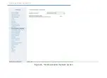
Страница 73: ...violation alarm device Specify the speed km h and acceleration m s2 values upon exceeding of which a speed mode violation signal is to be generated Pressing the Additional parameters hyperlink Fig 24 allows you to set up the following parameters 1 Duration of on impulse in seconds 2 Duration of off impulse in seconds 3 Impulse number 4 Switch on if duration is exceeding the value in seconds 5 If e...

Страница 74: ...Operating Manual Voyager 2N Figure 24 Output terminals section ...

Страница 75: ...ly after the battery compartment cover is taken off for diagnostics of tracker performance For energy saving purposes indicators are off when the tracker is fully assembled Whenever the Constant mode is chosen indicators are always on provided the tracker has active power supply It is not recommended for use in vehicles sensitive to elevated energy consumption while the engine is off It is not rec...

Страница 76: ...Operating Manual Voyager 2N Figure 25 Indication section ...

Страница 77: ...hrough GPRS use only GPRS for data transferring Only through Wi Fi use only Wi Fi for data transferring Wi Fi first then GPRS data transferring through Wi Fi is in priority If within 2 minutes does not appear an available network to connect data transmission will be done via GPRS i Please note that the change of the communication channel will be made only after reconnecting the device to the serve...

Страница 78: ...Operating Manual Voyager 2N Figure 26 Communication channels section ...

Страница 79: ...e Please clarify parameters with your monitoring service provider i If the eu ritm ru server is used do not change settings in this section The following values have to be specified Object number for connection to server when not using GEO RITM server Main coordinate receipt server IP address Password of the object to be connected to the server Main coordinate receipt server port Reserve coordinat...

Страница 80: ...Operating Manual Voyager 2N Figure 27 Coordinate Receipt Servers section ...

Страница 81: ...mobile object monitoring server are specified in the tracker You can specify connection parameters for both the main and reserve servers If the reserve server is not used you need to copy the main server settings to the reserve server configuration by either pressing Copy address and port to the reserve server or entering them manually If the server marked as main is unavailable the tracker tries ...

Страница 82: ...Operating Manual Voyager 2N Figure 28 EGTS protocol server configuration15 15 This example uses random EGTS servers and ports Please clarify connection parameters with your service provider ...

Страница 83: ...e connection to the monitoring server in case the mobile object enters a roaming zone In this case the object travel data are stored in the black box of the system and are later transferred to the monitoring system server after the object returns to its home mobile network Use of two SIM cards registered in different regions or countries allows constant receipt of data from any object that frequen...

Страница 84: ...tings of which should be used for automatic detection Enter parameters of available mobile networks in your region i Proper APN parameters can be requested from your mobile network operator Default APN settings may include data for the most common operators in your country but it might be neccessary to check this settings ...

Страница 85: ...Operating Manual Voyager 2N Figure 29 GPRS Parameters section ...

Страница 86: ... identification of drivers is available The MAC addresses connected to the access point of mobile devices are recorded in the history of the tracker Configure the settings of the tracker s Wi Fi module in this section Module details The Module details page provides basic information about the Wi Fi module of the tracker Fig 30 1 SDK Wi Fi version presumes an integrated Wi Fi module 2 The functiona...

Страница 87: ...Operating Manual Voyager 2N Figure 30 Module details ...

Страница 88: ...ity No WPA WPA2 Network signal strength the level of signal attenuation You can connect to any available network To do so click on the desired network with the left mouse button and then click on the Connect to network link that appears See Fig 30 In this case you will be automatically redirected to the page Network Connection where you have to complete the connection by entering your password and...

Страница 89: ...Operating Manual Voyager 2N Figure 31 Networks monitoring ...

Страница 90: ...to To do so enter your name and password and click the Connect link Check the Connect automatically box so that the tracker automatically connects to the selected network every time when it turns on To minimize the possibility of entering an incorrect password tick the Show password field and the password will be displayed completely To disconnect from the current network click the Disconnect link...

Страница 91: ...Operating Manual Voyager 2N Figure 32 Connection to a network ...

Страница 92: ... point IP address with the default value 192 168 4 1 4 4 SSID the broadcast network name By default the network is called Ritm the last 8 digits of IMEI 5 Security Open WPA2 6 Password set a password to restrict the ability to connect to an access point 7 Channel this parameter is determined automatically If you know the number of the free channel then specify it i How to create a strong password ...

Страница 93: ...Operating Manual Voyager 2N Figure 33 Access point ...

Страница 94: ...nsmitted to Rostransnadzor servers and from 2014 and on ERA GLONASS system servers The section features the following options Identifier of home telematics group Specify an identifier in the corresponding field Allow EGTS statistics transfer To allow restrict EGTS statistics transfer select deselect the corresponding field Allow unscheduled transferring of alarm events to the EGTS Server Check thi...

Страница 95: ...data upon transfer using the EGTS protocol Disabled encryption is off GOST data are encrypted according to the algorithm described in GOST 28147 Press Additionally enter the encryption key and fill out the replacement table if necessary Alternative Press Additionally enter the encryption key ...

Страница 96: ...Operating Manual Voyager 2N Figure 34 EGTS parameters section ...

Страница 97: ...ocol is shown This section is used for reference and contains the following information Number of all confirmed points Number of all lost points Number of server connections Number of the latest point in the tracker log Number of the oldest point in the tracker log Date and time of the oldest point UTC Number of the transfered point Pressing Clear statistics nullifies the EGTS statistics ...

Страница 98: ...Operating Manual Voyager 2N Figure 35 EGTS statistics section ...

Страница 99: ...e call from then engineering or any other number if engineering numbers are not used and calling from any number is allowed The maximum length of voice call can be setup After the set time passes the call is automatically disconnected Transfer of data to the monitoring system server pauses for the duration of a call 16 The dispatch unit is sold separately The dispatch unit cannot be connected to L...

Страница 100: ...Operating Manual Voyager 2N Figure 36 Dispatch section ...

Страница 101: ...group 01 Traffic control commands 02 Orders confirmations driver s query answers 03 Info messages List of formalized messages to be shown on indicator s display upon receipt of message from dispatch center Code Message Traffic control commands 01 Traffic schedule delay enter the schedule 02 Ahead of traffic schedule enter the schedule Orders confirmations driver s query answers 11 Firefighting veh...

Страница 102: ...are necessary to attract attention of a vehicle s driver while the life time ensures the message is displayed on a screen in the driver s cabin for the period specified When several editable messages are edited and sent together by clicking Send all the transferred messages would be shown on the vehicle s screen in the order corresponding to the submitted message line number The status of a formal...

Страница 103: ...Operating Manual Voyager 2N Figure 37 Message Terminal section ...

Страница 104: ...an RS 232 serial port17 i Colors and shades may differ from the original image depending on the hardware version of the screen Figure 38 Touch Screen The screen enables depiction of the following Alphanumeric messages transmitted onboard of a vehicle from the dispatch center Messages selected by driver from the screen memory for transmission to the dispatch center 17 Not available in LIGHT and LIG...

Страница 105: ...age groups lists 2 Transfer of selected message s text to the dispatch center 3 Confirmation of receipt of the text message by a dispatcher LEFT 1 Begin selection of formalized messages group from the top of the list 2 Show the previous formalized message message group in the list of messages groups move to the top of the list RIGHT 1 Begin selection of formalized messages group from the bottom of...

Страница 106: ...he line 03 Messages to the dispatcher 04 Traffic delay 05 Help request Texts of formalized messages for transmission from driver to dispatch center Code Message Emergency call 01 Fire emergency alarm 02 Police alarm 03 Ambulance alarm 04 Road Police alarm 05 Tow truck alarm 06 Road Security Police alarm 07 Call to the dispatcher for voice to voice communication Leaving the line 08 Leaving Technica...

Страница 107: ...p request 24 The number of trips completed 25 Time of the lunch start and end 26 Shift turnaround time 27 Knocking off time 28 Current traffic schedule Reserved automatically generated codes Code Message Group 00 Automatic messages and messages not from the list 29 Code is sent automatically after message receipt and displaying it on the indicator screen Answer 30 Automatically generated at pressi...

Страница 108: ...n idle timeout passes in the course of the selection procedure If a message from a dispatcher is received during the formalized message selection procedure the message is stored the selection is not cancelled and the dispatcher s message is shown immediately after work with formalized messages has been finished and the screen has been put to the standby mode On Screen Display of Messages from Disp...

Страница 109: ...l number Frequency Audio duration 1 3000 Hz 0 1 s 2 3000 Hz 0 5 s 3 3000 Hz 0 1 s 0 1 s 4 3000 Hz 1 s Audio signals are received together with text messages Sound is played while the message is displayed on the screen Whenever the screen control button is pressed this action is reconfirmed by Audio Signal 1 in all cases but Confirmation of selection of a formalized message to be sent by the driver...

Страница 110: ...overall size of the record in the field One history record size bytes and the total possible number of records in history These parameters are used by technicians to configure the tracker Removal of certain parameters may affect the capability for displaying reports and routes in the user interface of the monitoring system Any change in the history structure deletes all history previously recorded...

Страница 111: ...Operating Manual Voyager 2N Figure 39 History structure section ...

Страница 112: ...tted Status of record transmission to the server Transferred Not transferred History can be exported to txt kml and json files When exporting to a json file you can use export filters by date and record number To do so choose the export format JSON Date or JSON Record Number respectively To save data to a file use corresponding hyperlinks Numbers of recorded history pages are shown under the table...

Страница 113: ...Operating Manual Voyager 2N Figure 40 History section ...

Страница 114: ... detected and matches a number in the list In order to connect to the tracker the number detected by the tracker upon connection should exactly match a number in the engineering numbers list If a GPRS connection is active at the moment the incoming call is received it would be aborted upon connection from an engineering number for a conversation using a dispatcher s intercom or for configuration o...

Страница 115: ...Operating Manual Voyager 2N Figure 41 Engineering Numbers section ...

Страница 116: ...back file copy on device Check the box Continuous Play if you want to play an unlimited number of times the specified file Click Stop to stop playing You can play a copy of the file on the local computer for example for the checking if the exact path to the file is unknown To do so click the Copy of file for playback in the window that opens select the desired file and click Playback file copy on ...

Страница 117: ...Operating Manual Voyager 2N Figure 42 Autoinformer section ...

Страница 118: ...version 36 this standard is used in Volvo and Renault trucks In this case connection does not involve the CAN pin of the tracker but the RS 485 pin This way to connect using the J1708 standard follow the actions described below 1 Connect the CAN bus of the vehicle to the RS 485 pin of the tracker 2 In the I O Ports section select the RS485 port and assign the BUS J1708 bus to it Fig 44 3 In the CA...

Страница 119: ...Operating Manual Voyager 2N Figure 43 CAN section Vehicles data transfer bus ...

Страница 120: ...sensors section 2 Vehicle units allowing to control opening closing doors during stops for example vehicle door limit switches are connected to the tracker discrete inputs 3 Upon opening doors the tracker receives the appropriate signal from the door limit switches and transmits it to the connected sensors The sensors start to calculate passengers After closing doors the sensors are deactivated ti...

Страница 121: ...ntended to minimize false sensor operations for example in case of the faulty vehicle door which does not close at the first attempt i For proper operation of sensors The number of vehicle doors should correspond to the number of functional areas Each functional area should have a unique number corresponding to the vehicle door number Numbers of functional areas should be in consecutive order When...

Страница 122: ...Operating Manual Voyager 2N Figure 44 CAN section Automatic Passenger Counting sensor IRMA MATRIX ...

Страница 123: ...el sensor Connection of fuel gauge unit Strela D232 Input Expander V EB Connection of Ritm manufactured Input Expander V EB Expander allows you to increase quantity of discrete inputs of the tracker to 12 RS485 Not in use This port is not used Ritm bin protocol Connection of Ritm manufactured devices Omnicomm fuel gauge unit or equivalent model Connection of Omnicomm fuel gauge units or equivalent...

Страница 124: ...Operating Manual Voyager 2N Figure 45 I O Ports section ...

Страница 125: ...r covered parking The map shows a pin with the approximate location of the tracker and a circle showing the inaccuracy margin for the location detected using base station data To reduce the zone of possible location data from all detected base stations may be shown on the map To do so select Show all base stations The tracker location will be at the intersection of all circles To automatically upd...

Страница 126: ...Operating Manual Voyager 2N Figure 46 Map section ...

Страница 127: ...e latest update version download and install all previous versions To update the tracker software follow the steps below 1 Select a version of the firmware to update in Version 2 Click the Start updating hyperlink to begin downloading the software to the tracker The tracker will restart after firmware installation is completed After restarting make sure the Tracker Details section contains the cur...

Страница 128: ...Operating Manual Voyager 2N Figure 47 Available Update section ...

Страница 129: ... is used for downloading the device configuration to a file Receive data from navigation receiver When this button is pressed the response field will show the response directly from the GPS GLONASS receiver Master code If you need to limit access for connection of the universal configuration software use a four character master code In this case this code will be required for connecting to the tra...

Страница 130: ...www ritm ru 130 of 173 Operating Manual Voyager 2N Forced reset of device If the tracker has stopped working as expected reset it ...

Страница 131: ...Operating Manual Voyager 2N Figure 48 Service section ...

Страница 132: ...the tracker uses the eu ritm ru server If you do not yet have a user account perform the registration procedure by following the Registration hyperlink i Follow the wizard hints during the registration procedure In case of questions please refer to GEO RITM User Manual document Enter your account In the main menu select the Mobile Objects section Click Add an object Fig 49 Figure 49 Button Add an ...

Страница 133: ...www ritm ru 133 of 173 Operating Manual Voyager 2N After add an object procedure is finished the new object will appear in the Mobile Objects section of the main menu Fig 50 Figure 50 GEO RITM Service ...

Страница 134: ...ion cable to vehicle systems see pin connection table Connection points of the device main power supply to the vehicle s on board system should be selected so as to provide device power supply when the ignition is switched off and the ground connection is de energized if necessary directly from the vehicle s battery Insulate unused pins Connect the connection cable with a 20 pin connector to the d...

Страница 135: ...he windshield When choosing the installation location please note that windows covered with film and electrically heated windows decrease the signal reception strength thus adversely affecting object location detection The recommended tracker installation locations in light motor vehicles and trucks are shown in Figures 51 and 52 respectively Figure 51 Recommended installation locations in a light...

Страница 136: ...ectors Fig 53 for connection of antennas and external devices is shown on the back side of the battery compartment cover Figure 53 20 pin tracker connector We recommend doing all connections with the tracker battery removed External power should be supplied only after connection of antennas and the 20 pin connector ...

Страница 137: ...perature gauge 9 Input 3 discrete analog frequency Universal input Input type discrete analog or frequency is set up in the configuration software The discrete input features a configurable polarity The analog and frequency inputs can be connected to fuel consumption and level meters 10 Input 4 discrete analog frequency 11 Input 1 discrete The discrete input features a configurable polarity 12 Inp...

Страница 138: ...wer Fig 54 should be done via pins 1 power positive terminal and 2 power negative terminal of the 20 pin connector The connection should be done using a cable with the minimum cross section of 0 75 mm2 The power supply circuit should be protected with a 5 A fuse Figure 54 3 1 2 4 5 12 9 7 8 10 11 6 13 14 16 15 17 18 19 20 5 А _ АКБ Power connection diagram BATTERY ...

Страница 139: ... grounded and recovers upon opening For connection of a panic button Fig 55 use a button with NO pins Figure 55 3 1 2 4 5 12 9 7 8 10 11 6 13 14 16 15 17 18 19 20 Panic button connection diagram Adjust parameters for discrete inputs in the Input terminals section Specify the following parameters Input designation mechanism ignition or panic button Input signal polarity Signal duration for triggeri...

Страница 140: ...uring the fuel level and temperature in vehicle fuel tanks Figure 56 LLS AF20160 fuel gauge Connection of gauges is done via the RS 485 interface Connect Fig 57 the white orange wire from Pin 5 of the gauge connector to Pin 16 RS 485 A of the 20 pin tracker connector and the white blue connector from Pin 6 of the tracker connector to Pin 15 RS 485 B of the tracker Connect power to Pins 1 of the ga...

Страница 141: ...www ritm ru 141 of 173 Operating Manual Voyager 2N Figure 57 А А В В С С 3 1 2 4 5 12 9 7 8 10 11 6 13 14 16 15 17 18 19 20 12 24 В Fuel gauge connection diagram 12 24 V ...

Страница 142: ... 8 10 11 6 13 14 16 15 17 18 19 20 12 24 V А А В В С С 12 24 V 2 fuel gauge connection diagram In the I O Ports section choose the designation Omnicomm fuel gauge unit or equivalent model for the port RS 485 Set a unique number to each of connected gauges in the gauge configuration software ...

Страница 143: ...ocess involves tank refuelling from the empty to full condition with a certain refuelling step and further registration of device readings into the calibration table the Calibration table hyperlink in the Fuel tab You can find gauge readings necessary for filling out the calibration table in the History section Choose the refuelling step manually based on the volume and shape of the fuel tank Take...

Страница 144: ... and 4 the chosen number of calibration steps 6 Fill out the calibration table with the values gathered please see a filled example of the table in Figure 59 7 After the table has been filled out click Save Figure 59 Calibration table EPSILON ES4 The tracker may work with four digital fuel gauge units EPSILON ES4 Fig 60 The EPSILON ES4 fuel gauge unit is designed for measuring the fuel level in ve...

Страница 145: ...B of the tracker connector to Pin 15 RS 485 B of the tracker Connect power to Pins U of the gauge 12 24 red wire and Pin U GND black wire To connect the ES4 sensor use a terminating resistor of 240 Ohm Connect the resistor in parallel to the sensor See Figure 61 The using EPSILON ES4 sensor similar to the sensor Omnicomm LLS AF20160 In the I O Ports for RS485 port select the appointment of fuel ga...

Страница 146: ...www ritm ru 146 of 173 Operating Manual Voyager 2N Figure 61 B А U U 3 1 2 4 5 12 9 7 8 10 11 6 13 14 16 15 17 18 19 20 12 24 V EPSILON ES4 R 240 Ohm Fuel gauge connection diagram ...

Страница 147: ...nd the white wire from Pin 2C of the gauge connector to Pin 2 of the tracker In the Input terminals section of the configuration software use Inputs 3 and 4 to configure frequency analog gauge parameters Specify the following parameters Input type Analog Frequency Input designation Fuel level sensor Fuel level measurement Constant or With ignition on Use the tracker configuration software to verif...

Страница 148: ...www ritm ru 148 of 173 Operating Manual Voyager 2N Figure 62 А А В В С С 3 1 2 4 5 12 9 7 8 10 11 6 13 14 16 15 17 18 19 20 12 24 V Frequency analog gauge connection diagram ...

Страница 149: ... connector connect the CAN H pin of the tracker with the corresponding CAN H pin of the ODB2 connector of your vehicle Fig 63 Figure 63 3 1 2 4 5 12 9 7 8 10 11 6 13 14 16 15 17 18 19 20 Connection to vehicle CAN bus i If your vehicle does not have an ODB2 connector contact your vehicle dealer manufacturer for details on connection to the CAN bus Use the tracker configuration software to verify th...

Страница 150: ...to the monitoring software GEO RITM In the interface of the GEO RITM you can build the appropriate report of the passenger traffic i The figure 64 shows a possible connection diagram The diagram can be changed depending on particular needs For example another number of sensors can be connected but not over 8 and the connection order of door limit switches can be changed For more details on using t...

Страница 151: ... 15 17 18 19 20 GND 24 V 24 V GND CAN L CAN H R 120 Ω Connector IRMA MATRIX sensor door 1 Connector IRMA MATRIX sensor door 2 IRMA MATRIX sensor door 3 Connector Door 2 limit switch Door 3 limit switch Door 1 limit switch ADC1 DIN1 ADC2 IRMA MATRIX sensors connection diagram ...

Страница 152: ...gure 65 Dispatch unit with PTT button To connect a dispatch unit to the tracker use the special connector supplied with the package Connection of the tracker Fig 66 should be done using the guidlines located in connectors In the Dispatch section of the configuration software select the Turn on dispatch field You can also select the maximum duration of a voice call by default the duration is unlimi...

Страница 153: ...www ritm ru 153 of 173 Operating Manual Voyager 2N Figure 66 Dispatch unit connection diagram 3 1 2 4 5 12 9 7 8 10 11 6 13 14 16 15 17 18 19 20 PTT button ...

Страница 154: ...n 8 of the tracker Connect the power negative terminal of the temperature sensor to Pin 2 of the tracker Fig 67 Figure 67 3 1 2 4 5 12 9 7 8 10 11 6 13 14 16 15 17 18 19 20 _ Temperature sensor connection diagram Temperature sensor readings are shown in the Sensors section Temperature sensor Use the tracker configuration software to verify that the 1 Wire temperature sensor is added to the History...

Страница 155: ...ositive terminal of the reader to Pin 8 of the tracker Connect the common power negative terminal of the reader to Pin 2 of the tracker Fig 68 Figure 68 3 1 2 4 5 12 9 7 8 10 11 6 13 14 16 15 17 18 19 20 TM reader connection diagram Use the tracker configuration software to verify that the TM Key and Reader parameters are added to the History Structure section ...

Страница 156: ...iver and GSM modem are on and the tracker connects to the monitoring system server for data transfer You can monitor the coordinate detection procedure by indicators on the tracker enclosure Frequent short blinks 5 times per second Coordinates have not been determined Blinks once per second Coordinates have been determined If the tracker has already been configured for operation with the monitorin...

Страница 157: ... is within its mobile network coverage Check the normal operation and balance of the SIM cards Make sure the GPRS channel data transfer service is enabled Verify GPRS access point settings Clarify connection parameters with your mobile network operator Check connection parameters to the monitoring system server entered in the tracker Make sure the object account in the monitoring system is properl...

Страница 158: ...itm ru Operating Manual Voyager 2N 158 of 173 Maintenance At least twice per year visually inspect the tracker for enclosure or connector damage At least once per month check the SIM card accounts for funds ...

Страница 159: ...ng the tracker in extremely hot cold conditions i e under the vehicle windshield direct sunlight Do not expose the tracker to strong vibration or quick shock loads If dirty wipe the tracker with a clean dry cloth Do not use chemicals or detergents Do not paint the tracker as foreign paint and material particles may get inside and bring it out of service or adversely affect the directional pattern ...

Страница 160: ...ker should be transported in packaging in closed vehicles Storage and transportation conditions should conform to those listed in class IE12 of EN 60721 3 1 Storage premises should be free of current conducting dust acid and alkaline fumes corrosive gases and gases harmful to insulation ...

Страница 161: ...ion Warranty repairs of the tracker are done throughout the life cycle The manufacturer s warranty does not cover the battery The tracker life cycle is 6 years provided the operating conditions are observed The manufacturer shall not be responsible for quality of data links provided by GSM operators and Internet service providers The manufacturer reserves the right for modification of the tracker ...

Страница 162: ... should be disposed of separately from household waste Figure 69 Symbol of separate disposal from household waste Used batteries may not be Disposed of together with household waste Stored together with batteries of other types Dismantled and exposed to physical impact Burnt Bring used batteries to toxic waste drop off station ...

Страница 163: ...time After this time to configure the tracker via SMS will require re sending a command MASTER Send all the necessary commands together with the command MASTER specified separated by commas e g MASTER 1234 FOLLOW ON It is recommended to use this method as less dependent on the quality of communication 2 If the tracker has not been assigned a Master code will be accepted and implemented any receive...

Страница 164: ...to 9 Master 1234 or MASTER 1234 REBOOT Restart device REBOOT FOLLOW Enable Disable Follow mode ON enable OFF disable FOLLOW ON FOLLOW OF RITM Activation of the connection to RITM server ON enable RITM ON EGTS Activation of the connection to EGTS server EGTS is open protocol for geolocation description is in open access can be used for integration ON enable EGTS ON ...

Страница 165: ... to set up 2 servers the same time SERVER1 dev1 eu ritm ru 9426 SERVER2 dev2 eu ritm ru 9426 OBJECT Object number for connection to the server Number 1 65535 OBJECT 12345 PASSWORD Password for connection to the server 8 symbols including digits and latin letters PASSWORD password GUARD Enable disable mode send alarm events ON enable OFF disable GUARD ON ...

Страница 166: ...3 Main EGTS server 4 Reserve EGTS server The response to the command is a SMS message in the following format Object number Password IP address or domain name Port CONNECT_SERVER 1 VR_PACK_SIZE Request of the current time interval of navigation data transmission to the server VR_PACK_SIZE 1 The response to the command is an SMS message that contains the number from 1 to 30 indicating the number of...

Страница 167: ...tocols 2 data transferring only in EGTS protocol 3 data transferring is off PROTOCOL_TYPE 1 GPRS_SIM Request of the current settings of GPRS connection GPRS_SIM SIM card where SIM card the number of installed SIM card 1 or 2 The response to the command is a SMS message in the following format GPRS phone number APN User Password where GPRS phone number the dial in number for establishing a GPRS ses...

Страница 168: ...1 only at motion 2 only at started engine 3 at motion or at started engine 4 at motion and at started engine Time 2 10 minutes 255 no recording over time Moving 50 100 meters Speed 100 300 km h VR_FILTER_TRACK 1 GPRS_APN_AUTO Request of the information about APN automatical configuration GPRS_APN_AUTO 1 The response to the command is an SMS message containing the number from 0 to 1 where 0 automat...

Страница 169: ...sion of memory chips VER_INFO 1 GET_IMEI Request of the IMEI GET_IMEI 1 The response to the command is a SMS message containing the IMEI of integrated GSM modem GET_IMEI 1 GET_NMEA_RMC Navigation data request GET_NMEA_RMC 1 The response to the command is a SMS message containing the string in the NMEA protocol with RMC data or the empty string if satellite signal receiver is disabled GET_NMEA_RMC ...

Страница 170: ... 1 pass123 dev1 eu ritm ru 9426 PROTOCOL_TYPE Specify the data transferring protocol type PROTOCOL_TYPE 1 X where X 0 data transferring only in RITM protocol 1 data transferring in RITM and EGTS protocols 2 data transferring only in EGTS protocol 3 data transferring is off PROTOCOL_TYPE 1 0 VR_PACK_SIZE Changing of the current time interval of navigation data transmission to the server equivalent ...

Страница 171: ...ed engine 4 at motion and at started engine Time 2 10 minutes 255 no recording over time Moving 50 100 meters Speed 100 300 km h VR_FILTER_TRACK 1 0 2 100 250 GPRS_SIM Configuring of the GPRS connection equivalent to specifying the options in section GPRS parameters GPRS_SIM SIM card GPRS phone number APN User Password where IM card the number of installed SIM card 1 or 2 GPRS phone number the dia...

Страница 172: ...on equivalent to specifying the options in section GPRS parameters GPRS_APN_AUTO 1 The value where The value 0 automatical configuration of APN is not used 1 automatical configuration of APN is used GPRS_APN_AUTO 1 1 REBOOT Remote tracker rebooting REBOOT 1 1 REBOOT 1 1 ...

Страница 173: ...escription 1 0 22 09 2016 Full revision of document 1 1 04 04 2017 The following sections were added A GPS SMS messages Communication channels Wi Fi parameters Autoinformer 1 2 05 06 2017 Appendix 1 was fixed 1 3 26 12 2017 Appendix 1 was fixed Information about IRMA MATRIX sensors was added ...

Отзывы: