


Chapter 3: Setting up the Interface and Test Board
34
RIM OEM Radio Modem for GSM/GPRS Wireless Networks
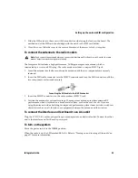
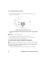
2. On the underside of the modem, on the connector, push the two black tabs up from the
connector to widen the opening.
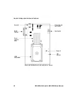
Underside of radio modem showing the 6-pin connector
3. With the blue side facing the Interface and Test Board, insert the end of the cable 6-pin cable into
the connector. Verify that the side with the bare pins is in direct contact with the pin side of the
connector.
4. Push the black tabs down toward the connector to secure the cable.
5. Repeat steps 2 through 4 to connect the 6-pin connector to the Interface and Test Board.
6. Re-attach the radio modem to the Interface and Test Board.
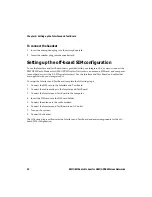
To connect the radio modem to the Interface and Test Board
The 22-pin flat interface cable supplies clean, regulated power to the radio and carries most of the
data and all of the voice between the Interface and Test Board and the radio modem. This cable also
carries control and status signals, such as
ONI
.
1. At the top of the radio modem, push the two black tabs up and away from the connector.
Note:
Do not force the cable into the connector.
Note:
This step is only necessary if the radio modem is not already connected to the Interface and Test Board.
Содержание 1802G
Страница 6: ...Important safety and compliance information 6 RIM OEM Radio Modem for GSM GPRS Wireless Networks ...
Страница 10: ...10 RIM OEM Radio Modem for GSM GPRS Wireless Networks ...
Страница 12: ...About this guide 12 RIM OEM Radio Modem for GSM GPRS Wireless Networks ...
Страница 24: ...Chapter 2 Getting started 24 RIM OEM Radio Modem for GSM GPRS Wireless Networks ...
Страница 75: ......
Страница 76: ... 2002 Research In Motion Limited Published in Canada ...


