


Setting up the off-board SIM configuration
Integrator Guide
33
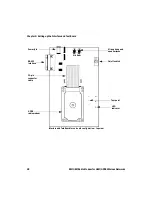
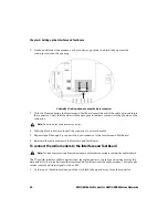
Interface and Test Board for off-board configuration— top view
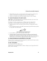
To connect the SIM card to the Interface and Test Board
The 6-pin flat SIM interface cable carries the data and power between the Interface and Test Board
SIM slot and the radio modem.
1. Remove the radio modem from the Interface and Test Board: unfasten the nuts and lift the radio
modem up and away from the Interface and Test Board.
Note:
This task only applies to the off-board SIM configuration.
Microphone and
On/off switch
Test point
LED
Power jack
RS-232
22-pin
GPRS
speaker jacks
interface
indicator
connector
radio modem
cable
6-pin
SIM card
connector
holder
Mic Spkr
Содержание 1802G
Страница 6: ...Important safety and compliance information 6 RIM OEM Radio Modem for GSM GPRS Wireless Networks ...
Страница 10: ...10 RIM OEM Radio Modem for GSM GPRS Wireless Networks ...
Страница 12: ...About this guide 12 RIM OEM Radio Modem for GSM GPRS Wireless Networks ...
Страница 24: ...Chapter 2 Getting started 24 RIM OEM Radio Modem for GSM GPRS Wireless Networks ...
Страница 75: ......
Страница 76: ... 2002 Research In Motion Limited Published in Canada ...


