background image

Chapter 3: Setting up the Interface and Test Board

30

RIM OEM Radio Modem for GSM/GPRS Wireless Networks

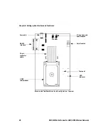
To insert the SIM card into the SIM card holder

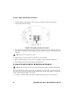
1. Turn the test board over to reveal the cut-out that provides access to the SIM card holder on the 

underside of the radio modem.

Underside of the test board showing the on-board SIM card holder

2. Slide the SIM card holder in the direction of the arrow to unlock it, and then lift the cover open.

Warning:

 To prevent damage to your SIM card, do not scratch or bend the card or expose it to static electricity 

or wet conditions.

Note:

 You must have a SIM card that is authorized for use by the appropriate GPRS network provider. The 

authorization must also allow access to the Access Point Name (APN) that will be targeted.

Содержание 1802G

Страница 1: ...RIM OEM Radio Modem for GSM GPRS Wireless Networks RIM 1902G and RIM 1802G Integrator Guide Version 1 2 ...

Страница 2: ...re protected by copyright international treaties and various patents including one or more of the following U S patents 6 278 442 6 271 605 6 219 694 6 075 470 6 073 318 D445 428 D433 460 D416 256 Other patents are registered or pending in various countries around the world Visit www rim net patents shtml for a current listing of applicable patents While every effort has been made to achieve techn...

Страница 3: ...Important safety and compliance information This section provides information on the following topics FCC compliance statement USA Industry Canada Certification EU Regulatory Conformance ...

Страница 4: ...generates uses and can radiate radio frequency energy and if not installed and used in accordance with the manufacturer s instructions may cause interference harmful to radio communications There is no guarantee however that interference will not occur in a particular installation If this equipment does cause harmful interference to radio or television reception which can be determined by turning ...

Страница 5: ... out in the interference causing equipment standard entitled Digital Apparatus ICES 003 of Industry Canada EU Regulatory Conformance This section applies to the RIM 1802G OEM Radio Modem for GSM GPRS Wireless Networks R6420GE Research In Motion Limited hereby declares that the device is in compliance with the essential requirements and other relevant provisions of Directive 1999 5 EC The original ...

Страница 6: ...Important safety and compliance information 6 RIM OEM Radio Modem for GSM GPRS Wireless Networks ...

Страница 7: ...etworks 13 GPRS network technology 14 About the RIM 1902G and RIM 1802G radio modems 14 Range of applications 15 Receiver sensitivity 16 Noise immunity 16 Powerful and efficient transmitter 17 Small size 17 CHAPTER 2 Getting started 19 About the Integrator Kit 20 Working with RIM 20 Integration overview 21 CHAPTER 3 Setting up the Interface and Test Board 25 Interface and Test Board components 26 ...

Страница 8: ...rs 42 CHAPTER 5 Power requirements 45 Load specifications 46 Power supply parameters 46 Ripple specification 46 Power requirements 47 Batteries 47 Plug in supplies 48 Automotive supplies 48 CHAPTER 6 Interface specification 49 RIM 1902G or RIM 1802G interface 50 AT Commands 50 SIM interface pins 51 Radio interface pins 52 Pins 1 to 4 52 Pins 5 to 22 52 Serial port 52 Pin descriptions 53 Turning on...

Страница 9: ... 60 Selecting an antenna 61 Antenna requirements 62 Antenna design considerations 62 Shielding 64 CHAPTER 8 Specifications 65 Power supply and typical current usage 66 RF properties 66 Serial communications 66 Mechanical and environmental properties 67 Audio 67 Index 69 ...

Страница 10: ...10 RIM OEM Radio Modem for GSM GPRS Wireless Networks ...

Страница 11: ... overview test board overview mounting requirements power battery requirements interfacing with the RIM radio modem antenna selection and placement This guide provides suggestions and precautions to ease the implementation of a wireless communication solution To discuss the technical integration of this radio modem contact RIM at oemsupport rim net Related documentation The Integrator Kit includes...

Страница 12: ...About this guide 12 RIM OEM Radio Modem for GSM GPRS Wireless Networks ...

Страница 13: ...Chapter 1 The RIM OEM Radio Modem for GSM GPRS Wireless Networks This section provides information on the following topics GPRS network technology About the RIM 1902G and RIM 1802G radio modems ...

Страница 14: ...dio modems The RIM OEM Radio Modem for GSM GPRS Wireless Networks sets a new standard for radio modem performance The radio modem s small size and weight makes it suitable for virtually any wireless data and voice application including handheld devices and mobile terminals Its multislot class allows for the highest allowable download rates using a single receiver on a GPRS network The RIM OEM Radi...

Страница 15: ... These benefits of these features are described below Range of applications RIM radio modems are designed to integrate easily into computing devices for a wide range of applications such as the following ones laptop computers vehicle tracking point of sale devices monitoring and telemetry applications ruggedized terminals vending machines handheld computers utility meters parking meters billboards...

Страница 16: ...902G and RIM 1802G typically have receiver sensitivities of 107 dBm with a 2 2439 bit error rate BER Noise immunity The RIM 1902G and RIM 1802G are not desensitized by the electromagnetic interference EMI or noise that is generated by the electronics of the terminal into which it is integrated As a result no special shielding is required between the radio and your device Noise immunity offers seve...

Страница 17: ...he RIM OEM Radio Modem for GSM GPRS Wireless Networks provides reliable transmission efficiency across the entire operating voltage range of 3 5 to 4 75 volts As a result batteries can be used even when they are near depletion The transmission efficiency also maximizes the radio coverage area throughout the life of the battery Small size Because of its single board design the RIM OEM Radio Modem f...

Страница 18: ...Chapter 1 The RIM OEM Radio Modem for GSM GPRS Wireless Networks 18 RIM OEM Radio Modem for GSM GPRS Wireless Networks ...

Страница 19: ...Chapter 2 Getting started This section provides information on the following topics about the Integrator Kit working with RIM integration overview ...

Страница 20: ...erface the radio modem to your computing device Working with RIM RIM has an experienced team to help you design and implement your wireless communication solutions If you need help getting started or if you have any questions about the radio technology or its integration into your platform contact the engineering development team Phone 519 888 7465 ext 5200 Fax 519 883 4940 Email oemsupport rim ne...

Страница 21: ...Integration overview Integrator Guide 21 Integration overview The following diagram illustrates the integration process ...

Страница 22: ...to obtain a SIM card Activate GPRS account Contact the appropriate network provider to activate the GPRS account Contact certification labs Learn about obtaining certification Radio frequency RF emitting products cannot be sold until you have the necessary government approvals Understanding what you are permitted to do before beginning your design will help you to avoid redesign costs Start develo...

Страница 23: ... assess performance and reliability Perform certification Choose a testing lab to perform appropriate certification For RIM 1902G FCC Industry Canada and PTCRB For RIM 1802G R TTE and GCF Pilot Beta release Contact RIM prior to the beta release of the product especially if the product has not been certified yet There are specific guidelines that must be followed prior to certification to confirm t...

Страница 24: ...Chapter 2 Getting started 24 RIM OEM Radio Modem for GSM GPRS Wireless Networks ...

Страница 25: ... Test Board This section provides information on the following topics Interface and Test Board components Setting up the Interface and Test Board on board SIM configuration Setting up the Interface and Test Board off board SIM configuration ...

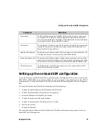
Страница 26: ...owing table describes Interface and Test Board components Component Description RS 232 interface The serial COM port on a computer and most terminal devices operates at RS 232 signal levels which are typically 12V This high voltage would damage the RIM OEM Radio Modem for GSM GPRS Wireless Networks which is typically integrated into a device that operates an asynchronous serial port at 3V The RS 2...

Страница 27: ...io Modem for GSM GPRS Wireless Networks requires a clean high current power source RIM uses a standard plug pack to provide the current that is necessary to operate the radio The voltage is converted into the necessary levels by the power supply section of the Interface and Test Board LED indicators The Interface and Test Board includes LED indicators to indicate the flow of data to and from the h...

Страница 28: ...IM OEM Radio Modem for GSM GPRS Wireless Networks Interface and Test Board for on board configuration top view Microphone and On off switch Test point LED Power jack RS 232 22 pin GPRS speaker jacks interface indicator connector radio modem cable Mic Spkr ...

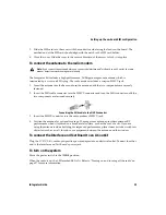
Страница 29: ...d of the 22 pin cable into the connector Verify that the side with the bare pins is in direct contact with the pin side of the connector 3 At the top of the radio modem push the black tabs down toward the connector to secure the cable 4 Repeat steps 1 through 3 for the 22 pin connector on the Interface and Test Board To connect the Interface and Test Board to the computer Use the straight through ...

Страница 30: ...Underside of the test board showing the on board SIM card holder 2 Slide the SIM card holder in the direction of the arrow to unlock it and then lift the cover open Warning To prevent damage to your SIM card do not scratch or bend the card or expose it to static electricity or wet conditions Note You must have a SIM card that is authorized for use by the appropriate GPRS network provider The autho...

Страница 31: ... cable to the MMCX connector 3 Insert the MMCX connector into the radio modem s MMCX jack 4 Position the antenna for optimal coverage The magmount antenna provides optimum RF performance when it is placed on a broad metal surface such as the roof of a car If you are using the antenna inside a building for improved performance place it near a window with few obstacles such as a wall furniture or eq...

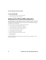
Страница 32: ...r device with a RS 232 serial interface Use the Interface and Test Board and cables that are supplied with your Integrator Kit To set up the Interface and Test Board complete the following steps 1 Connect the SIM card to the Interface and Test Board 2 Connect the radio modem to the Interface and Test Board 3 Connect the Interface and Test Board to the computer 4 Insert the SIM card into the SIM ca...

Страница 33: ...een the Interface and Test Board SIM slot and the radio modem 1 Remove the radio modem from the Interface and Test Board unfasten the nuts and lift the radio modem up and away from the Interface and Test Board Note This task only applies to the off board SIM configuration Microphone and On off switch Test point LED Power jack RS 232 22 pin GPRS speaker jacks interface indicator connector radio mod...

Страница 34: ...onnector to secure the cable 5 Repeat steps 2 through 4 to connect the 6 pin connector to the Interface and Test Board 6 Re attach the radio modem to the Interface and Test Board To connect the radio modem to the Interface and Test Board The 22 pin flat interface cable supplies clean regulated power to the radio and carries most of the data and all of the voice between the Interface and Test Board...

Страница 35: ...f the cable to the Interface and Test Board Connect the female end of the cable to the computer s COM port To insert the SIM card into the SIM card holder 1 Slide the SIM card holder in the direction of the arrow to unlock it and then lift the cover open 2 Slide the SIM card into the cover with the conductive side facing the leads on the board The notched end of the SIM card should align with the ...

Страница 36: ... is placed on a broad metal surface such as the roof of a car If you are using the antenna inside a building for improved performance place it near a window with few obstacles such as a wall furniture or equipment between the antenna and the window To connect the Interface and Test Board to an AC outlet Plug the 5V DC 2 4A center pin positive power adapter into an electrical outlet Connect the oth...

Страница 37: ...Radio Modem for GSM GPRS Wireless Networks This section provides information on the following topics Overview Environmental properties Storage temperature Operating temperature Physical properties Mounting methods Cables and connectors ...

Страница 38: ... Integrator Kit as a resource as you develop your application s hardware The Integrator Kit includes several components that can help you develop your product s housing and physically integrate the radio modem and associated hardware into your application These components consist of two 22 pin connector cables two 6 pin connector cables off board SIM configuration and two radio modem mechanical sa...

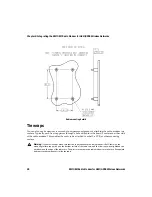
Страница 39: ...he following mounting methods bolts or standoffs tie wraps permanent industrial adhesive The following information is presented as a guide however applications can vary considerably A mechanical engineer can help you make sure that the mounting method that you choose is suitable for your application Bolts or standoffs The radio modem includes a hole in each corner which can be used to bolt the dev...

Страница 40: ...ole drilled into the board s surface on either side of the radio modem This enables the radio to be attached to a shell a PCB or other mounting surface Warning If you use tie wraps make sure that the surface beneath the radio modem is flat Otherwise the mounting surface can push up on the bottom surface of the radio case and the tie wraps when tightened can push down on the edge of the radio case ...

Страница 41: ...M configuration antenna connector Radio interface cable and connector The radio interface connector connects the radio modem to a serial computing device speaker and microphone and power supply Serial communication data control signals and power are carried on a flat 22 conductor 0 30 mm 0 012 inches thick flexible printed circuit FPC cable This cable has 1 mm centerline spacing that can plug into...

Страница 42: ...r casing This enables the antenna to be removed from the system without opening the device and it eliminates a source of strain on the radio s MMCX connector The antenna cable that you use should have low loss an impedance of 50 Ohm and an MMCX plug that mates with the RIM 1902G or RIM 1802G MMCX jack The other end of the cable can be any connector with an impedance of 50 Ohm An SMA screw on conne...

Страница 43: ...dance of 50 Ω and are suitable for use with the RIM 1902G or RIM 1802G Part number Cable or connector 11MMCX 50 2 1C 111 Straight MMCX connector 16MMCX 50 2 1C 111 Right angle MMCX connector 25SMA 50 2 25 111 SMA connector EZ Flex 405 Low loss matching 50W cable 133REEZ4 12 S2 1216 8 cable straight MMCX to SMA 133REEZ4 12 S2 1699 8 cable right angle MMCX to SMA ...

Страница 44: ...Chapter 4 Integrating the RIM OEM Radio Modem for GSM GPRS Wireless Networks 44 RIM OEM Radio Modem for GSM GPRS Wireless Networks ...

Страница 45: ...Chapter 5 Power requirements This section provides information on the following topics Load specifications Power requirements Batteries Plug in supplies Automotive supplies ...

Страница 46: ...ipple specification For best performance RIM recommends a ripple of less than 15 mV peak to peak measured at the radio end of the connector across the frequency range 60 Hz to 1 MHz The maximum ripple at the connector that can be tolerated is 20 mV peak to peak Except in special cases where there are several sources of ripple you should measure the ripple with an oscilloscope set to 1 MHz bandwidt...

Страница 47: ...ating temperature range RIM recommends using rechargeable nickel cadmium NiCad batteries to power the radio modem You can also successfully use nickel metal hydride NiMH and lithium ion Li cells However many of these cells work poorly at temperatures below freezing Battery specifications should be obtained from the manufacturer The cells that you use must meet the radio modem load specifications r...

Страница 48: ...tection These should have a value of 20V and be placed on the supply side of the regulator circuit Refer to Load specifications on page 46 for more information Automotive supplies If you plan to power the RIM 1902G or RIM 1802G from an automotive supply you must take steps to protect the radio modem from the intense power fluctuations that occur when an automobile starts You should use a circuit t...

Страница 49: ... specification This section provides information on the following topics RIM 1902G or RIM 1802G interface AT Commands SIM interface pins Radio interface pins Turning on and turning off the radio Loading firmware optional ...

Страница 50: ... Command Reference Guide which is included in the Integrator Kit AT Commands Command Description V 25ter The V 25ter commands correspond to the basic commands of AT Hayes compatible modems applicable for GSM 07 07 These commands include answering incoming calls switching modes and redialing GSM 07 07 The GSM 07 07 commands are used to remotely control GSM functionality including phone book functio...

Страница 51: ...ntinue proper operation Pin Description 1 VCC This line supplies the SIM card with power Verify that it leads to the VCC pin of the SIM card connector It might be necessary to filter noise on the line to prevent a fault from occurring Refer to the following diagram for an example 2 Reset This is an output from the radio Verify that it leads to the reset pin of the SIM card connector 3 Clock This i...

Страница 52: ...troduced to take advantage of the GPRS data network s underlying GSM voice infrastructure The differential nature of the analog lines provides high voice quality and noise immunity Pins 5 to 22 Input and output lines from pins 5 to 22 are 3V however they can also drive 3 3V systems All digital outputs will source a short circuit current of 3 mA Digital inputs have a current leakage of 1 mA Serial ...

Страница 53: ...e wireless network this line is low An AT command is available to change the function of this pin causing it to be asserted high when the radio is GPRS attached 7 8 Power supply These pins supply power to the radio Because the current requirement during transmission exceeds the current rating of a single line both lines 7 and 8 should be connected to the power supply Supplying power to these two l...

Страница 54: ... short circuit protected This line is low when the radio modem is off 13 TX2 Secondary Transmit This line is an input to the radio modem for RIM internal use only 14 RI Ring Indicate This line is an output from the radio modem It indicates an incoming call on the serial line When DTR is not asserted high the radio modem asserts RI low to indicate that it has data waiting for the computing device T...

Страница 55: ...al output from the radio modem The active data set ready DSR state of this line is low Your computing device can use DSR as a confirmation that the radio modem knows the state of the terminal 18 GND Ground This line should be tied to the system ground of the host unit Pin 9 should also be connected to ground 19 DTR Data Terminal Ready This line is a digital input to the radio The active data termi...

Страница 56: ...R rate AT command 21 RX Received data This line is an output from the radio modem Its idle no serial receive activity state is high This line is an asynchronous serial output from the radio modem and should be connected to the host terminal s receive data input This line carries data at at a maximum of 115 200 bps Parameters are 8 bits No parity 1 stop bit The baud rate can be changed using the AT...

Страница 57: ...dio to be off even though TURNON is asserted In this case you can turn on the radio by setting TURNON low and then high again Turning off the radio The RIM 1902G or RIM 1802G requires a controlled shutdown You can turn the radio modem off by de asserting TURNON Data that has been received by the radio modem from the network but has not been transferred to the computing device is not saved The data...

Страница 58: ... to design your application in such a way that allows the RIM firmware to be updated after your product is deployed in the field Because of its large size firmware cannot be updated wirelessly If you decide to implement the ability to update the firmware after the radio modem is deployed RIM can provide a command line programming utility that loads firmware into the radio modem If your device is n...

Страница 59: ...Chapter 7 Antenna selection This section provides information on the following topics Antenna terminology Selecting an antenna Antenna requirements Antenna design considerations Shielding ...

Страница 60: ...1W at 1900 MHz and 1800 MHz 0 8W at 850 MHz or 2W at900 MHz The antenna gain or loss results in an increase or decrease in this value The actual output from the antenna is called the effective radiated power ERP For example if the radio modem delivers 2W of power to a 2 3 dBd gain antenna the ERP is 2 0 10 2 3 10 3 4W the actual power radiated by the antenna in the direction of maximum gain and po...

Страница 61: ...a match However this shortening reduces the antenna efficiency and therefore the effective radiated power Selecting an antenna The antenna is one of the most important components of a wireless communication system The proper antenna maximizes the coverage area of the RIM 1902G or RIM 1802G The antenna that you choose should suit your project s needs There are many different antenna types and optio...

Страница 62: ...1802G hardware integration to be fully compatible with the RIM 902M and RIM 802D radio modems the antenna must be modular GPRS has several frequency bands 1900 1800 900 and 850 each of which requires its own antenna GPRS Mobitex and DataTAC networks have different center frequencies If the same antenna is used for all three networks receiver sensitivity is reduced Contact the RIM OEM Integration S...

Страница 63: ... from the antenna into the radio modem during transmission the antenna must be placed a minimum of 2 cm 0 8 away from the radio modem For best performance the antenna should be placed more than 5 cm 2 away from the radio modem Device position If the computing device is designed to sit on a surface the antenna should be as far from the bottom of the device as possible This reduces radio frequency R...

Страница 64: ...ed to provide any additional RF shielding between the radio modem and a computing device unless the environment contains an extreme level of RF noise In fact additional RF shielding is less important than making sure that the radio modem s power supply is free of high frequency electrical noise The antenna must be positioned so that the radiated energy is directed away from the computing device If...

Страница 65: ...ation on the following topics Power supply and typical current usage RF properties Serial communications Mechanical and environmental properties Audio Gain setting Frequency response voiceband filter Input output impedance Signal to noise distortion ratio ...

Страница 66: ...frequency 1850 1910 MHz 824 849 MHz 1710 1785 MHz 880 915 MHz Transmit power 1W at 1900 MHz 0 8W at 850 MHz 1W at 1800 MHz 2W at 900 MHz Receive frequency 1930 1990 MHz 869 894 MHz 1805 1880 MHz 925 960 MHz Receiver sensitivity 107 dBm typically 2 2439 BER 107 dBm typically 2 2439 BER Multislot class 8 8 Note As defined in the GSM specifications the radio modem s transmitter can reduce output powe...

Страница 67: ... g 1 23 oz including case Dimensions 42 0 by 67 5 mm 1 65 x 2 66 Thickness 8 4 mm 33 3V interface connectors 22 pin Flexible Printed Circuit FPC connector 6 pin FPC connector on board SIM configuration only Antenna cable connector MMCX Casing metal Recommended operating temperature 30 C to 75 C at 5 95 relative humidity non condensing Recommended storage temperature 40 C to 85 C Uplink 0 to 22 5 d...

Страница 68: ...00 Hz max of 34 dB 200 Hz typ of 1 1 300 3350 Hz min 0 2 dB max 0 1 dB 3400 Hz typ of 0 7 dB 4000 Hz typ of 39 dB 4400 Hz 75 dB Group delay 500 2500Hz min 300 µ max 600 µ Input 124 kohm Output minimum 330 ohm single ended 15 ohm differential maximum 470 pF single ended 100 pF differential Voiceband ADC minimum 69 dB PGA 0dB typical 77 dB Voiceband DAC minimum 47 dB PGA 0dB ...

Страница 69: ... modularity 62 orientation 63 position 63 positioning 31 36 62 proximity to active electronics 63 radiation efficiency 61 return loss 60 RF exposure requirements 63 selecting 61 shielding 64 size 61 SMA plug 31 36 42 transmission interference 62 transmit interference 63 vertical polarization 62 63 VSWR 60 antenna development overview 22 arrestor circuits 48 AT commands 50 attenuation 63 audio freq...

Страница 70: ...s return loss 60 voltage standing wave ratio WSWR 61 equivalent series resistance ESR 47 F FCC compliance statement 4 interference requirements 4 field trials overview 23 firmware loading 58 FPC cable 41 frequency response specifications 68 G gain 63 gain setting specifications 67 General Packet Radio Service 14 Global System for Mobile Communication 14 GND pin 53 55 58 GPRS radio modem batteries ...

Страница 71: ... interface connecting to 41 test board 27 interface and test board components 26 set up overview off board SIM 32 set up overview on board SIM 27 interface cable 22 pin 29 34 6 pin 33 SIM 42 interference FCC requirements 4 shielding 64 L LED indicators 27 loading firmware 58 M magmount antenna 31 36 mechanical properties specifications 67 MIC N pin 53 MIC P pin 53 microphone speaker jack 27 minimu...

Страница 72: ...lies 48 development 23 load specifications 46 plug in supply 48 specifications 66 test board 27 printed circuit board development overview 23 R radio coverage maximizing 17 radio interface cable 41 radio interface pins AGND 53 COV 53 CTS 54 description 53 DSR 55 DTR 55 58 GND 53 55 58 MIC N 53 MIC P 53 ONI 54 57 power supply 53 RI 54 RTS 55 RX 56 58 RX2 54 SPK N 53 SPK P 53 TRI 54 TURNON 53 TX 56 ...

Страница 73: ...M interface pins 51 warning 30 35 SIM interface pins Clock 51 Ground 51 Input Output 51 Reset 51 VCC 51 SIM test board incorporation 52 SIM interface cable 42 single board design 17 single use batteries 48 size GPRS radio modem 17 SMA connector 31 36 SMA plug 31 36 42 software development 22 specifications audio 67 environmental properties 67 frequency response 68 gain setting 67 input output impe...

Страница 74: ...icators 27 microphone speaker jack 27 on off switch 26 power supply 27 RS 232 interface 26 SIM card 27 test points 26 test points 26 tie wraps 40 transmit interference 63 transmitter efficiency 17 TRI pin 54 turning off the radio modem 57 turning on the radio modem 57 TURNON pin 53 TX pin 56 58 TX2 pin 56 V VCC pin 51 voltage minimum requirements 46 regulators 48 W workflow integration 21 Z zener ...

Страница 75: ......

Страница 76: ... 2002 Research In Motion Limited Published in Canada ...

Отзывы: