background image

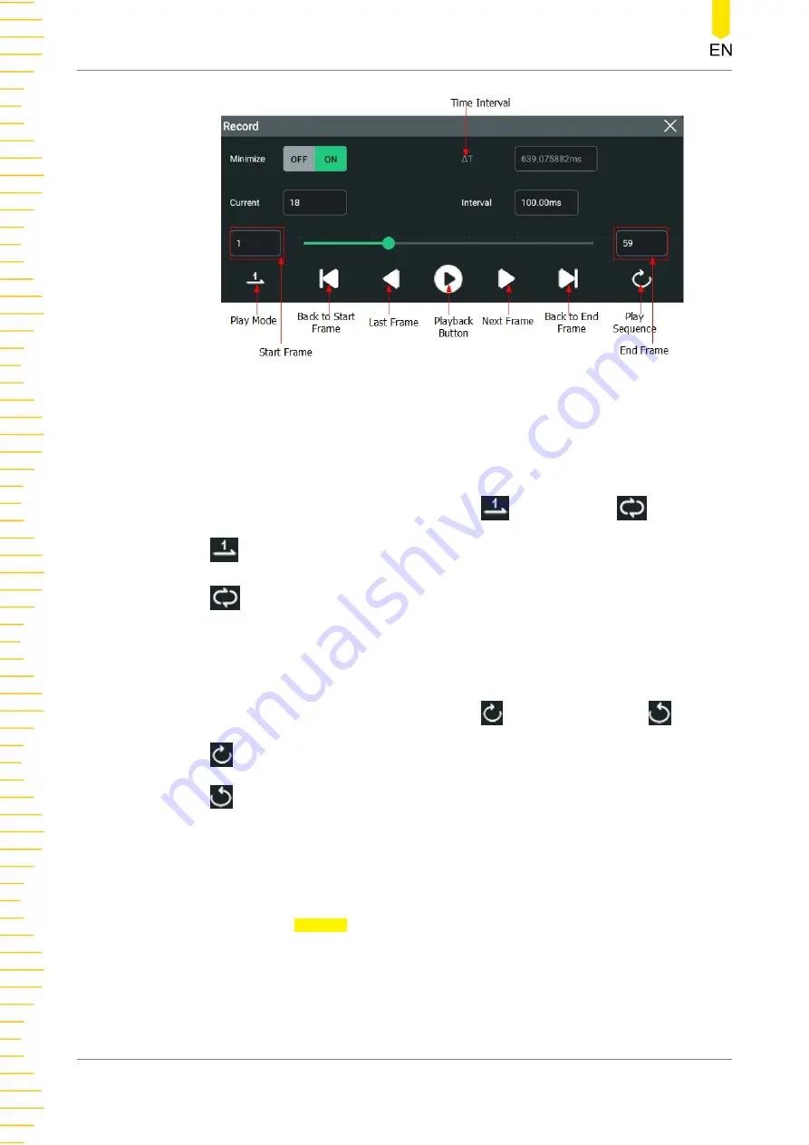
Figure 16.2 Minimized "Play" Menu

Before playing the waveforms, set the following parameters.

1. Play Mode

You can play the waveforms in single mode (

) or cycle mode (

).

-

: plays from the start frame to the end frame, and then stops automatically.

-

: plays from the start frame to the end frame, then such playback operation

is repeated until you stop it manually.

2. Play Sequence

You can play back the waveforms clockwise (

) or counterclockwise (

).

-

: plays from the start frame to the end frame.

-

: plays from the end frame to the start frame.

3. Interval

The playback interval indicates the time interval between the frames during the
playing process.

Click or tap the Interval input field, then use the pop-up numeric keypad to set
the time interval between frames. You can also use the corresponding
multipurpose knob to set the value. The available range is from 1 ms to 10 s.

4. Start Frame

 Waveform Recording and Playing

HDO1000 User Guide

200

Copyright ©RIGOL TECHNOLOGIES CO., LTD. All rights reserved.

Содержание HDO1000 Series

Страница 1: ......

Страница 2: ...ce RIGOL shall not be liable for either incidental or consequential losses in connection with the furnishing use or performance of this manual as well as any information contained Any part of this doc...

Страница 3: ...mensions 11 4 3 To Prepare for Use 12 4 3 1 Tilting the Oscilloscope for Easier Viewing 12 4 3 2 Connecting to Power 13 4 3 3 Turn on Checkout 13 4 3 4 Replacing the Fuse 14 4 3 5 Setting the System L...

Страница 4: ...To Specify the Skew 48 5 12 To Turn the Channel Label Display On Off 49 6 Horizontal System 50 6 1 To Adjust the Horizontal Time Base 50 6 2 To Adjust the Horizontal Position 51 6 3 Zoom Mode Delayed...

Страница 5: ...rithmetic Operation 115 9 2 Function Operation 118 9 3 FFT Operation 121 9 4 Logic Operation 126 9 5 Digital Filter 130 10 Measurements 134 10 1 Measurement Parameter 134 10 1 1 Time Parameters 135 10...

Страница 6: ...the Source 168 13 3 To Create a Mask 168 13 4 To Set the Output Form of the Test Results 168 13 5 To Start or Stop the Pass Fail Test Operation 169 13 6 Display the Statistics of the Test Results 170...

Страница 7: ...rd Options 198 16 3 Play Options 199 17 Search and Navigation 202 17 1 Search 202 17 2 Navigation 204 18 Display Control 207 18 1 Display Type 207 18 2 Persistence Time 208 18 3 Waveform Intensity 208...

Страница 8: ...fig 239 20 6 SelfCal 240 20 7 Option List 241 20 8 Quick Action Settings 241 20 9 Self check 243 21 Remote Control 246 21 1 Remote Control via USB 247 21 2 Remote Control via LAN 247 21 3 Remote Contr...

Страница 9: ...re 4 12 User Interface 26 Figure 4 13 Tap Gesture 29 Figure 4 14 Pinch Stretch Gesture 29 Figure 4 15 Drag Gesture 30 Figure 4 16 English Input Interface 31 Figure 4 17 Chinese Input Interface 32 Figu...

Страница 10: ...Trigger 79 Figure 8 10 Pattern Trigger Setting Menu 79 Figure 8 11 Duration Trigger 81 Figure 8 12 Duration Trigger Setting Menu 82 Figure 8 13 Timeout Trigger 84 Figure 8 14 Timeout Trigger Menu 84...

Страница 11: ...Waveform Display Window of the Operation Results 115 Figure 9 3 Arithmetic Operation Menu 116 Figure 9 4 Operation Result Display Window 116 Figure 9 5 Function Operation Menu 119 Figure 9 6 Operatio...

Страница 12: ...Menu 163 Figure 13 1 Pass Fail Test Menu 167 Figure 13 2 Pass Fail Test Interface 170 Figure 14 1 Schematic Diagram of Parallel Decoding 172 Figure 14 2 Parallel Decoding Menu 173 Figure 14 3 Parallel...

Страница 13: ...lay Setting Menu 207 Figure 18 2 Vector Display 208 Figure 19 1 Image Saving Setting Menu 212 Figure 19 2 Waveform Saving Setting Menu 214 Figure 19 3 Setup Saving Setting Menu 215 Figure 19 4 Load Se...

Страница 14: ...24 Table 9 2 Logic Operation 128 Table 14 1 Bus Setting 174 Table 19 1 BIN File Format 216 Table 19 2 File Header 217 Table 19 3 Waveform Header 217 Table 19 4 Waveform Data Header 219 Table 19 5 Fact...

Страница 15: ...be connected to earth ground Do not connect the ground lead to high voltage Improper way of connection could result in dangerous voltages being present on the connectors controls or other surfaces of...

Страница 16: ...never operate the instrument in an explosive atmosphere Keep Instrument Surfaces Clean and Dry To avoid dust or moisture from affecting the performance of the instrument keep the surfaces of the inst...

Страница 17: ...ING It calls attention to an operation if not correctly performed could result in potential injury or hazard CAUTION It calls attention to an operation if not correctly performed could result in damag...

Страница 18: ...tationary motors with permanent connection to a fixed installation Measurement category IV is for measurements performed at the source of a low voltage installation Examples are electricity meters and...

Страница 19: ...tion overvoltage category I refers to signal level which is applicable to equipment measurement terminals connected to the source circuit Among these terminals precautions are done to limit the transi...

Страница 20: ...pened with mild detergent or water Avoid having any water or other objects into the chassis via the heat dissipation hole When cleaning the LCD take care to avoid scarifying it CAUTION To avoid damage...

Страница 21: ...l authorities for disposal or recycling information You can click on the following link https int rigol com services services declaration to download the latest version of the RoHS WEEE certification...

Страница 22: ...r operating knobs effectively prolonging its service life Standard USB Device Host LAN and HDMI interfaces HDO1000 series digital oscilloscope is designed to meet the designing debugging and testing r...

Страница 23: ...he menu key icon For example indicates the DEFAULT key 2 Menu The menu item is denoted by the format of Menu Name Bold Character Shading in the manual For example Setup indicates the Setup sub menu un...

Страница 24: ...2 channel and 4 channel models which share the same operation methods Unless otherwise specified this manual takes the 4 channel model HDO1104 as an example to illustrate the basic operation methods...

Страница 25: ...eplacement of the instrument 2 Inspect the instrument In case of any mechanical damage missing parts or failure in passing the electrical and mechanical tests contact your RIGOL sales representative 3...

Страница 26: ...scilloscope s rear feet to tilt the oscilloscope to stabilize it for easier operation and viewing Flip in the tabs for storage or transporting when not using the instrument Please see the figure below...

Страница 27: ...to power on the instrument During the start up process the instrument performs a series of self tests After the self test the splash screen is displayed Restart Click or tap Restart Then a prompt mes...

Страница 28: ...trument and remove the power cord 2 Insert a small straight screwdriver into the slot at the power socket and pry out the fuse holder gently 3 Remove the fuse 4 Insert the proper fuse into the fuse ho...

Страница 29: ...ope on the front panel as shown in the figure below 2 Connect the ground alligator clip or spring of the probe to the circuit ground terminal and then connect the probe tip to the circuit point to be...

Страница 30: ...hen click or tap Auto 5 Observe the waveform on the display In normal condition you should see a square waveform similar to the waveform shown in the figure below Figure 4 8 Square Waveform Signal 6 T...

Страница 31: ...is as follows 1 Perform step 1 2 3 and 4 in Function Inspection 2 Check the displayed waveforms and compare them with waveforms shown in the figure below Figure 4 9 Probe Compensation 3 Use the probe...

Страница 32: ...labels and parameter settings system state prompt messages and other information 2 Multipurpose Knobs Non menu operation When not operating on the menu you can rotate the knob 1 to adjust the waveform...

Страница 33: ...inated In this point you can rotate the knob to adjust the value or press the knob to restore the parameter to the default value When using the virtual numeric keypad or drop down list you can rotate...

Страница 34: ...trigger mode to Single is the default setup key Press this key to restore the oscilloscope s default settings is the clear key Press this key to clear all waveform on the display If the oscilloscope...

Страница 35: ...waveform up or down on the display Press this knob to reset the vertical position to zero Vertical SCALE is the vertical scale knob Turn this knob to modify the value of vertical divisions of the gra...

Страница 36: ...the horizontal position trigger position to move the waveforms horizontally Press the knob to reset the horizontal position to default Horizontal SCALE is the horizontal scale knob Turn the knob to ch...

Страница 37: ...hannel Input Terminals Attach probes to these connectors for analog signal inputs For two channel models HDO1072 HDO1102 HDO1202 only two input terminals are available 14 USB HOST Port This series sup...

Страница 38: ...nt capture rate Pass Fail In the pass fail test the instrument will output a pulse via the AUX OUT connector when a passed or failed waveform is detected during the pass fail test 2 EXT TRIG BNC conne...

Страница 39: ...m can be built quickly Then you can control the instrument through using Web Control to send the SCPI commands to control the instrument When update is available you can perform online upgrading for t...

Страница 40: ...tus of the instrument 3 Horizontal Timebase Label Displays the current horizontal time base Click or tap this label to enter the horizontal setting menu 4 Sample Rate Memory Depth Label Displays the c...

Страница 41: ...icon When a USB storage device is detected will be displayed LAN icon When the LAN interface is successfully connected is displayed Sound icon In the Utility menu click or tap Setup Beeper to enable o...

Страница 42: ...ience The actions supported by the touch screen controls include tapping pinching stretching as well as dragging 4 5 1 Tap Use one finger to tap the symbol or characters on the screen slightly as show...

Страница 43: ...rm the following operation Pinching stretching in the horizontal direction can adjust the horizontal time base of the waveform Pinching stretching in the vertical direction can adjust the vertical sca...

Страница 44: ...mon parameter setting methods are as follows Method 1 Some parameters can be adjusted by rotating the front panel knobs Method 2 Click or tap the input field of a specified parameter then a virtual ke...

Страница 45: ...ase letter first use the Caps key to switch between the upper case and lower case mode If the Caps key is selected input the upper case letter with the virtual keypad If not first click or tap the Cap...

Страница 46: ...st and then input the new characters You can directly move the cursor to the character to be modified or deleted delete the desired character or input the new characters after deleting the unwanted ch...

Страница 47: ...ew more Chinese characters for you to choose Select the desired Chinese character and then the selected character will be displayed in the input area 4 Modify or delete the unwanted characters that ha...

Страница 48: ...ter All the input letters will be displayed in the Name Input Area 3 Input the lower case letter Refer to the operation specified in the previous step If the Caps key is not selected directly input th...

Страница 49: ...You can also rotate the multipurpose knob 1 or 2 to move the cursor and select the desired value and unit Then press the knob to input the selected value or unit Figure 4 19 Numeric Keypad After you...

Страница 50: ...o the lock hole vertically turn the key clockwise to lock the oscilloscope and then pull the key out Figure 4 20 To Use the Security Lock NOTE Please do not insert other objects into the security lock...

Страница 51: ...enter the utility function menu Click or tap Options to view the options currently installed Install the option The option license is a string of fixed characters The license file should be in specif...

Страница 52: ...e same USB storage device but the USB storage device can store the option license file of several different instruments You are not allowed to modify the licensed filename During the installation proc...

Страница 53: ...n Then the menu as shown in the figure below is displayed Figure 5 1 Vertical Menu 5 1 To Enable or Disable the Analog Channel Enable the analog channel When a signal is connected to CH1 you can enabl...

Страница 54: ...ertical menu to activate it Disable the analog channel You can disable the analog channel by the following methods If CH1 has been enabled and activated you can press on the front panel to disable it...

Страница 55: ...scale clockwise to reduce the scale and counterclockwise to increase Enable the touch screen function and then adjust the vertical scale with the pinch stretch gesture on the touch screen For details...

Страница 56: ...l offset information as shown in the following figure in the channel status label at the bottom of the screen will change accordingly The adjustable range of the vertical offset is related to the curr...

Страница 57: ...oupling mode is GND the DC and AC components of the signal under test are blocked After selecting the coupling mode the currently selected coupling mode is displayed in the channel status label at the...

Страница 58: ...at the bottom of the screen as shown in the figure below TIP Bandwidth limit can not only reduce the noise but also can attenuate or eliminate the high frequency components of the signal 5 6 To Speci...

Страница 59: ...turned on the trigger e g Edge trigger Pulse trigger or Slope trigger edge or polarity will be changed 5 8 To Set Probe The analog channel of this oscilloscope supports passive probes For detailed te...

Страница 60: ...ratio is 1X The probe ratio values available are as shown in the following table Table 5 1 Probe Ratio Menu Attenuation display amplitude of the signal actual amplitude of the signal 0 001X 0 002X 0...

Страница 61: ...e difference in the delays between the probes known as skew can cause great cable delay errors in measurement results To eliminate this problem this series oscilloscope provides the deskew function Cl...

Страница 62: ...e measurement results In Vertical menu click or tap the Up Down arrow icon at the right side of the input field of Bias to increase decrease the bias value or use the corresponding multipurpose knob t...

Страница 63: ...ument uses the channel number to mark the corresponding channel by default For ease of use you can also set a label for each channel For example Click or tap the channel status label at the bottom of...

Страница 64: ...at the top of the screen to enter the Horizontal menu Figure 6 1 Horizontal Menu 6 1 To Adjust the Horizontal Time Base Horizontal time base also called the horizontal scale refers to the time of each...

Страница 65: ...stment You can also press the front panel Horizontal SCALE knob to toggle between coarse adjustment and fine adjustment Coarse adjustment Click or tap the icon at the right side of the input field of...

Страница 66: ...ponding multipurpose knob to set the horizontal position or use the icons at the right side of the input field of Position to increase or decrease the value as shown in the figure below You can also c...

Страница 67: ...portion of the display that is not ghosted shows the normal display of the waveform Its horizontal time base called the main time base is indicated in the label at the upper left corner of the displa...

Страница 68: ...TIP The zoomed time base should be smaller than or equal to the main time base Horizontal System HDO1000 User Guide 54 Copyright RIGOL TECHNOLOGIES CO LTD All rights reserved...

Страница 69: ...the acquisition label A icon at the top of the screen Normal In Normal acquisition mode the oscilloscope samples the signal at a fixed time interval to rebuild the waveform This mode yields the best d...

Страница 70: ...ge rate in acquisition memory When you select High Res mode click or tap the bits drop down button to select 14 default or 16 The bandwidth of the selected bit is displayed behind the box TIP The aver...

Страница 71: ...de Mosaic The whole waveform view is divided into several blocks and each waveform segment is displayed in each block in sequence A maximum of 80 frames can be displayed on the screen at a time in thi...

Страница 72: ...ent model and the current channel mode For two channel models HDO1072 HDO1102 and HDO1202 the oscilloscope provides up to 2 GSa s real time sample rate in single channel mode and 1 GSa s real time sam...

Страница 73: ...too low the waveform reconstructed from the sample data does not reflect all the actual signal information 7 4 Memory Depth Memory depth refers to the number of points that the oscilloscope can store...

Страница 74: ...ime base a higher memory depth can ensure a higher sample rate In Horizontal menu click or tap the Mem Depth drop down button to select the memory depth The default setting is 10k The selected memory...

Страница 75: ...display Right when the horizontal time base is modified the waveform will be expanded or compressed horizontally relative to the rightmost position of the display Trigger when the horizontal time base...

Страница 76: ...the X axis in the XY window Click or tap the drop down button of Source Y to select the source channel of the Y axis in the XY window In the Add Window menu you can also configure Source Z Source Z as...

Страница 77: ...ween the two channels The definitions of A B C and D are shown in the figure above The phase deviation angle is obtained that is arcsin A B or arcsin C D If the principal axis of the ellipse is within...

Страница 78: ...can enter the Trigger menu in the following ways Press the front panel key to enter the trigger menu In Vertical System menu click or tap the Trigger button to enter the trigger menu Click or tap the...

Страница 79: ...is displayed in the the trigger information label at the top of the screen In Runt Trigger Slope Trigger and Window trigger you need to set the upper and lower limits of the trigger level Two trigger...

Страница 80: ...he acquisition is initiated via the front panel key the process repeats if the acquisition is initiated via the key it stops after finishing a single acquisition you can pan and zoom the currently dis...

Страница 81: ...tap the Force button in the trigger menu or press the front panel key to force a trigger event 8 4 Trigger Coupling Trigger coupling determines what part of the signal is passed to the trigger circut...

Страница 82: ...w set the holdoff time to be greater than t1 but less than t2 Figure 8 2 Trigger Holdoff Click or tap the trigger information label as shown in the figure below at the top of the screen or press the f...

Страница 83: ...1 Edge Trigger Edge trigger identifies a trigger on the trigger level of the specified edge on the input signal Trigger Type Click or tap the Type drop down button to select Edge Figure 8 3 Edge Trig...

Страница 84: ...level Trigger Mode In Sweep select Auto Normal or Single as the trigger mode For details refer to Trigger Mode Trigger Parameter Setting You can refer to Trigger Coupling Trigger Holdoff and Noise Re...

Страница 85: ...evel Figure 8 4 Positive Negative Pulse Width Trigger Type Click or tap Type drop down button to select Pulse Figure 8 5 Pulse Width Trigger Setting Menu After a trigger type is selected the current t...

Страница 86: ...h of the input signal is greater than the specified lower limit of pulse width and smaller than the specified upper limit of pulse width When you select Negative for polarity for trigger condition the...

Страница 87: ...tails refer to descriptions in Trigger Level The current trigger level is displayed in the trigger information label at the top of the screen 8 7 3 Slope Trigger Slope triggering sets the oscilloscope...

Страница 88: ...s refer to Trigger Source The selected trigger source is indicated in the trigger information label at the top of the screen Only when you select the channel that has signal inputs as the trigger sour...

Страница 89: ...condition the oscilloscope triggers when the negative slope time of the input signal is greater than the specified lower limit time and smaller than the specified upper limit time Slope Time Setting I...

Страница 90: ...tion label at the top of the screen 8 7 4 Video Trigger The video signal can include image information and timing information which adopts different standards and formats This series can trigger on th...

Страница 91: ...ard Frame Frequency Frame Scan Type TV Scan Line NTSC 30 Interlaced Scan 525 PAL SECAM 25 Interlaced Scan 625 480p 60Hz 60 Progressive Scan 525 576p 50Hz 50 Progressive Scan 625 720p 60Hz 60 Progressi...

Страница 92: ...an also use the front panel trigger level knob or the corresponding multipurpose knob to set the trigger level For details refer to descriptions in Trigger Level The current trigger level is displayed...

Страница 93: ...down button to select Pattern Figure 8 10 Pattern Trigger Setting Menu After a trigger type is selected the current trigger setting information including trigger type trigger source and trigger level...

Страница 94: ...els in the pattern are set to X the oscilloscope will not trigger sets the pattern to the rising edge of the channel selected sets the pattern to the falling edge of the channel selected The Left Righ...

Страница 95: ...the trigger information label at the top of the screen 8 7 6 Duration Trigger In duration trigger the oscilloscope identifies a trigger condition by searching for the duration of a specified pattern...

Страница 96: ...the top of the screen Only when you select the channel that has signal inputs as the trigger source can you obtain a stable trigger Pattern Setting The following three patterns are available 1 sets th...

Страница 97: ...e is from 100 ps to 9 9 s You can also use the corresponding multipurpose knob to set the upper lower limit The lower time limit must be smaller than the upper time limit triggers when the duration of...

Страница 98: ...8 13 Time Out T Time Out T Figure 8 13 Timeout Trigger Trigger Type Click or tap the drop down button of Type to select Timeout Figure 8 14 Timeout Trigger Menu After a trigger type is selected the c...

Страница 99: ...that the signal remains idle before the signal passes through the trigger level Click or tap the input field of Timeout and then use the pop up numeric keypad to set the timeout value of Timeout trigg...

Страница 100: ...pe Click or tap the drop down button of Type to select Runt Figure 8 16 Runt Trigger Setting Menu After a trigger type is selected the current trigger setting information including trigger type trigge...

Страница 101: ...ou can also use the corresponding multipurpose knob to modify the value triggers when the runt pulse width is greater than the lower limit and smaller than the upper limit of pulse width Click or tap...

Страница 102: ...trigger level The instrument triggers when the input signal passes through the high trigger level or the low trigger level Trigger Type Click or tap the drop down button of Type to select Over Figure...

Страница 103: ...exits the specified trigger level range Time triggers when the accumulated hold time since the input signal entered the specified trigger level range is equal to the window time After you select this...

Страница 104: ...meets the preset time limit as shown in the figure below Edge A and Edge B must be two neighboring edges T Source A Source B Edge A Edge B Figure 8 18 Delay Trigger Trigger Type Click or tap the drop...

Страница 105: ...l inputs as the trigger source can you obtain a stable trigger Edge B Select the trigger edge type Rising or Falling of Source B in Delay trigger in the EdgeB item Set the trigger condition Sets the t...

Страница 106: ...The lower time limit must be smaller than the upper time limit Level Selection and Setting After the trigger condition setting is completed you need to adjust the trigger level to correctly trigger th...

Страница 107: ...ers when the setup time or hold time is smaller than the preset time T1 T2 Data Source Clock Source T2 is the hold time T1 is the setup time Edage The data type is H Figure 8 20 Setup Hold Trigger Tri...

Страница 108: ...e Select the effective pattern of the data signal in the Data Type item It can be set to H high level or L low level Trigger Condition Sets the Setup Hold trigger condition in the When item Setup the...

Страница 109: ...on label at the top of the screen Level B Click or tap the input field of Level B to input the level of Source B with the pop up numeric keypad You can also use the corresponding multipurpose knob or...

Страница 110: ...r a trigger type is selected the current trigger setting information including trigger type trigger source and trigger level is displayed in the trigger information label at the top of the screen as s...

Страница 111: ...the pop up numeric keypad to set the value of N in Nth edge trigger You can also use the corresponding multipurpose knob to set the value The available range is from 1 to 65 535 Trigger Mode In Sweep...

Страница 112: ...ger Type Click or tap the drop down button of Type to select RS232 Figure 8 25 RS232 Trigger Setting Menu After a trigger type is selected the current trigger setting information including trigger typ...

Страница 113: ...and then use the pop up numeric keypad to set the data of RS232 trigger You can also use the corresponding multipurpose knob to set the value Baud Rate Set the baud rate of data transmission i e spec...

Страница 114: ...screen 8 7 14 I2C Trigger I2C is a 2 wire serial bus used to connect the microcontroller and its peripheral device It is a bus standard widely used in the microelectronic communication control field...

Страница 115: ...descriptions in Trigger Source The current trigger source is displayed in the trigger information label at the top of the screen Only when you select the channel that has signal inputs as the trigger...

Страница 116: ...2C trigger You can also use the corresponding multipurpose knob to set the value Data the trigger searches for the specified data value on the data line SDA When this event occurs the oscilloscope wil...

Страница 117: ...can refer to Noise Rejection to set the noise rejection under this trigger type Level Selection and Setting After the trigger condition setting is completed you need to adjust the trigger level to co...

Страница 118: ...PI trigger after the CS or timeout condition is satisfied the oscilloscope triggers when the specified data is found When using SPI trigger you need to specify the CLK clock sources and MISO data sour...

Страница 119: ...ock Trigger Condition Select the desired trigger condition in When With CS if the CS signal is valid the oscilloscope will trigger when the data SDA satisfying the trigger conditions is found Click or...

Страница 120: ...l is displayed in the trigger information label at the top of the screen Level B Click or tap the input field of Level B to input the level of MISO with the pop up numeric keypad You can also use the...

Страница 121: ...layed in the trigger information label at the top of the screen as shown in the figure below The information will change based on the trigger settings Source Selection Click or tap the drop down butto...

Страница 122: ...ignal Baud Rate Click or tap the drop down button of Baud to select the preset baud rate The available baud rates include 10 kbps 20 kbps 33 3 kbps 50 kbps 62 5 kbps 83 3 kbps and etc Sample Position...

Страница 123: ...he following parameters Click or tap the input field of Data and then the Format interface is displayed You can set the data bit that needs to be operated on For details refer to descriptions in I2C T...

Страница 124: ...the top of the screen 8 7 17 LIN Trigger This series can trigger on the sync field of LIN signal and can also trigger on the specified identifier data or frame The data frame format of the LIN bus is...

Страница 125: ...and Both Baud Rate Click or tap the drop down button of Baud to select the preset baud rate The available baud rates include 1 2 kbps 2 4 kbps 4 8 kbps 9 6 kbps 19 2 kbps and etc Sample Position Sampl...

Страница 126: ...ified ID and data that meet the preset conditions are both found When Data ID is selected you need to set the Data Bytes and ID Sleep triggers when the sleep frame is found Wakeup triggers when the wa...

Страница 127: ...te can be output from AUX OUT connector each time a trigger is generated by the oscilloscope If this signal is connected to a waveform display device to measure the frequency the measurement result is...

Страница 128: ...he Toolbar at the upper right corner of the screen to enter the Math menu Click or tap the Math1 Math4 label at the bottom of the screen and the corresponding math window appears on the screen as show...

Страница 129: ...tion In the Math menu click or tap the Operator drop down button to select the desired math operation The arithmetic operations supported by this oscilloscope include A B A B A B and A B A B adds the...

Страница 130: ...lick or tap the Operation on off switch to enable the display of the arithmetic operation result window The source and the vertical scale parameters are displayed at the top of the window as shown in...

Страница 131: ...set the vertical offset in the following ways In Vertical menu rotate the corresponding multipurpose knob on the front panel or click or tap the icon at the right side of the input field of Offset to...

Страница 132: ...vailable function operation types of this oscilloscope include Intg Diff Sqrt Lg Base 10 Exponential Ln Exp Abs and AX B Intg calculates the integral of the selected source For example you can use int...

Страница 133: ...enable or disable the display of the operation result window The source and the vertical scale parameters are displayed at the top of the window as shown in the figure below Figure 9 6 Operation Resul...

Страница 134: ...tical scale Please refer to Front Panel Overview to configure the front panel multipurpose knobs Offset Offset is used to set the vertical offset of the operation result You can set the vertical offse...

Страница 135: ...click or tap Smooth input field and use the pop up numeric keypad to set the number of smooth times for the differential operation You can also use the corresponding multipurpose knob to set the valu...

Страница 136: ...cy range and resolution are displayed at the top of the window as shown in the figure below FFT resolution is the quotient of the sample rate and the number of FFT points If the number of FFT points i...

Страница 137: ...ine the frequency range Span Center frequency span to center frequency Span specifies the frequency range represented by the width of the display Divide the frequency span by 10 to obtain the frequenc...

Страница 138: ...eakage can be considerably minimized when a window function is used The oscilloscope provides 6 FFT window functions which have different characteristics and are applicable to measure different wavefo...

Страница 139: ...Better frequency resolution Narrow band signal and that has strong noise interference Color Grade Click or tap the Color Grade on off switch to enable disable the color grade display of FFT operation...

Страница 140: ...e sorting mode By default it is Amp Order Click or tap Export then the save setting interface is displayed You can export the peak search results to the internal memory or the external USB storage dev...

Страница 141: ...R operation of two binary bits are shown in Table 9 2 Logic Operation A B Performs logic XOR operation on the waveform voltage values of the specified sources point by point and displays the results I...

Страница 142: ...are displayed at the top of the window as shown in the figure below Figure 9 11 Operation Result Display Window Source Click or tap the drop down button of SourceA or SourceB to select CH1 CH2 CH3 or...

Страница 143: ...e analog signal on the source Click or tap the Sensitivity input field to set the sensitivity with the pop up numeric keypad or use the corresponding multipurpose knob to set the value For details ref...

Страница 144: ...mit frequency to pass BandPass only allows the signals whose frequencies are higher than the current lower limit frequency and lower than the current upper limit frequency to pass BandStop only allows...

Страница 145: ...at the right side of the input field of Scale to increase or decrease the scale value You can also click or tap the input field to input a specific value with the displayed numeric keypad Close the me...

Страница 146: ...rresponding multipurpose knob to set the value HighPass click or tap the c input field and use the pop up numeric keypad to set the lower limit frequency or use the corresponding multipurpose knob to...

Страница 147: ...lts For setting methods refer to descriptions in To Turn the Channel Label Display On Off Grid For setting methods refer to the descriptions in To Set the Screen Grid Math Operation Copyright RIGOL TE...

Страница 148: ...oscilloscope allows you to set the measurement source enable or disable the all measurement function the statistical function and etc You can make quick measurements for many waveform parameters The...

Страница 149: ...the time between the threshold middle value of a rising edge to the threshold middle value of the next falling edge Width indicates the time between the threshold middle value of a falling edge to th...

Страница 150: ...hold Upper Limit Threshold Lower Limit Negative Pulse Count It is specified as the number of negative pulses that fall from above the threshold upper limit to below the threshold lower limit 1 n 2 Neg...

Страница 151: ...t is specified as the number of falling edges that fall from above the threshold upper limit to below the threshold lower limit 1 n 2 Falling Edge Count n Threshold Upper Limit Threshold Lower Limit M...

Страница 152: ...edge of Source A occurred after the falling edge of Source B 4 Delay f r indicates the time difference between the threshold middle values of the falling edge of Source A and the rising edge of Source...

Страница 153: ...etween the threshold middle values of the falling edge of Source A and the rising edge of Source B The phase formula is as follows 360 sourceA R F R F Period B DelayA B PhaseA Wherein PhaseARBR repres...

Страница 154: ...m or in the gating area The formula is shown as follows n x Average n i i 1 Wherein xi is the ith point and n is the number of points being measured 11 VRMS indicates the root mean square value on the...

Страница 155: ...sum of the area of the whole waveform within the screen Period Area indicates the area of the first period of waveform on the screen The unit is V s The area of the waveform above the zero reference...

Страница 156: ...requency Rise Time Fall Time Width Width Duty Duty Positive Pulse Count Negative Pulse Count Rising Edge Count Falling Edge Count Tvmax Tvmin Slew Rate and Slew Rate Measurements HDO1000 User Guide 14...

Страница 157: ...ement Items Other Delay r r Delay r f Delay f r Delay f f Phase r r Phase r f Phase f r and Phase f f Figure 10 6 Other Measurement Items Measurements Copyright RIGOL TECHNOLOGIES CO LTD All rights re...

Страница 158: ...ble at least one auto measurement parameter and the number of cursors will change with the measurement parameter enabled TIP When no measurement parameter is selected or there is no source input the i...

Страница 159: ...ultipurpose knob to set the value When the lower limit is set to be greater than or equal to the current middle value a prompt message Set at upper limit is displayed Then the oscilloscope will automa...

Страница 160: ...switch to enable or disable the statistical function This oscilloscope can make a statistics and display the current values of the multiple parameters as shown in the figure below Click or tap any mea...

Страница 161: ...input signal you can click or tap the function navigation icon at the lower left corner of the screen and select Auto to enable the waveform auto setting function and open the auto setting function me...

Страница 162: ...onfig TIP The waveform auto setting function requires that the frequency of the signal should be greater than or equal to 35 Hz the amplitude greater than or equal to 5 mV If not meeting the condition...

Страница 163: ...l dotted line is displayed at the right section of the screen In the XY cursor mode Y cursor is used to measure the waveform amplitude of CH2 You can enable cursor measurements in the following ways C...

Страница 164: ...ally to measure the value of the waveforms of the specified source at the current cursor If the settings for the parameter such as the cursor type and measurement source are different the measurement...

Страница 165: ...Its adjustable range is limited within the screen Click or tap the AX BX on off switch to turn on off adjusting the horizontal position of Cursor A and Cursor B X cursors simultaneously The horizontal...

Страница 166: ...cursors Cursor A and Cursor B to measure the X and Y values on two different sources respectively When the cursors are moved horizontally vertically the markers will position on the waveform automati...

Страница 167: ...current track axis By default it is X X When the X cursor position is adjusted Y cursor will automatically track the intersection point between X cursor and source signal Y When the Y cursor position...

Страница 168: ...of Cursor A and Cursor B Y cursors simultaneously The vertical spacing between Cursor A and Cursor B Y cursors remains unchanged You can also use the touch screen or the front panel multipurpose knob...

Страница 169: ...Remove to close the cursor measurement result display window at the right side of the screen 10 6 3 XY Mode In the Cursors menu click or tap XY for the Mode item to enable the XY cursor measurement fu...

Страница 170: ...ously Click or tap to select Y under the Select item to set the Y value for the specified cursor Click or tap the input field of AY and use the pop up numeric keypad to set the Y value at Cursor A Cli...

Страница 171: ...Result Window In Cursors menu click or tap Remove to close the cursor measurement result display window at the right side of the screen Measurements Copyright RIGOL TECHNOLOGIES CO LTD All rights res...

Страница 172: ...select DVM in the displayed Analyse menu to enable the DVM measurements After the DVM measurements are enabled the DVM label displaying the current voltage value and voltage mode appears in the Resul...

Страница 173: ...ot mean square value of the acquired data with the DC component removed DC displays the average value of the acquired data AC DC RMS displays the root mean square value of the acquired data Set the Li...

Страница 174: ...or tap Remove in the DVM setting menu to disable the function 11 2 Frequency Counter The frequency counter analysis function provides frequency period or edge event counter measurements on any analog...

Страница 175: ...the resolution by using the pop up numeric keypad You can also use the corresponding multipurpose knob to set the value The resolution ranges from 3 bits to 6 bits By default it is 5 bits The greater...

Страница 176: ...and a window is displayed Click or tap Reset Stat in the window to reset the statistics 11 2 3 Remove the Measurement Click or tap the Counter label in the Result bar and a window is displayed Click o...

Страница 177: ...Reference Waveform Menu When the Ref function is enabled you can select different colors for reference waveforms set the source of each reference channel adjust the vertical scale and offset of the r...

Страница 178: ...ton in the function navigation menu or press the front panel key to clear the reference waveforms of all the reference channels 12 3 To Set the Ref Waveform Display After clicking or tapping SaveToRef...

Страница 179: ...input field of Label to set the label of the specified reference channel with the pop up numeric keypad 12 4 Export and Import Operation To Export to Internal or External Memory You can save the curre...

Страница 180: ...or external USB storage device to the internal instrument and display the file on the screen Click or tap Import to enter the reference waveform file loading interface Set the Format In the file load...

Страница 181: ...r tap the function navigation icon at the lower left corner of the screen to open the function navigation Then click or tap the Pass Fail button to enter the PassFail setting menu You can also press t...

Страница 182: ...ge device when detected and apply them to the current pass fail test function Click or tap Load to enter the file loading interface Click or tap the input field of File Path to load the specified test...

Страница 183: ...t the oscilloscope will execute once a pass fail test is detected Stop stop sampling when a failed event is found Beeper the beeper sounds an alarm when a failed event is found irrelevant with the on...

Страница 184: ...e right side of the screen You can click or tap the icon at the lower right corner of the screen to hide the Result sidebar The test results statistics include the number of failed frames the number o...

Страница 185: ...Click or tap Remove then the pass fail function is disabled Pass Fail Test Copyright RIGOL TECHNOLOGIES CO LTD All rights reserved HDO1000 User Guide 171...

Страница 186: ...code1 Decode2 Decode3 and Decode4 this chapter takes Decode1 as an example for illustration Click or tap Decode to enter the Decode menu Click or tap the Decode button in the toolbar to enter the Deco...

Страница 187: ...o set a threshold Click or tap the input field of Threshold and then use the pop up numeric keypad to set the threshold You can also use the corresponding multipurpose knob to set the value The range...

Страница 188: ...to 4 0 Default CH1 CH4 Set the Threshold Level To judge logic 1 and logic 0 of the buses you need to set a threshold for each analog channel CH1 CH4 When the channel signal amplitude is greater than...

Страница 189: ...Event Table The event table displays the decoded data and the corresponding decoding information in time order in the form of a table It can be used to observe relatively longer decoded data The deco...

Страница 190: ...splay format of Data in the event table The available options include Hex Dec Bin or ASCII 14 2 RS232 Decoding RS232 serial bus consists of the transmitting data line TX and the receiving data line RX...

Страница 191: ...pe to select RS232 then configure the parameters for RS232 decoding Figure 14 6 RS232 Decoding Menu Bus Status Click or tap the Bus Status on off switch to enable or disable the bus decoding Quickly a...

Страница 192: ...arity Positive Uses negative logic High level is logic 0 and low level is logic 1 Negative Uses positive logic High level is logic 1 and low level is logic 0 Set the baud rate Click or tap the drop do...

Страница 193: ...s transmitted first MSB indicates Most Significant Bit transmission sequence i e the highest bit of the data is transmitted first bit0 bit1 bit2 bit3 bit4 bit5 bit6 bit7 bit7 bit6 bit5 bit4 bit3 bit2...

Страница 194: ...the event table will also be changed The displayed decoded data information in the bus is related to the value of the horizontal time base Reducing the horizontal time base can help you view the deta...

Страница 195: ...tes applying the trigger settings to the specified decoding setting Click or tap Copy Trig to apply the trigger settings to the specified decoding setting 14 3 1 Source Setting Set the clock channel s...

Страница 196: ...the R W bit When With is selected the R W bit will be included in the address information and located at the lowest bit when Without is selected the R W bit will not be included in the address informa...

Страница 197: ...play format of Data in the event table The available options include Hex Dec Bin or ASCII Address information in decoding For I2C bus each frame of data starts with the address information read addres...

Страница 198: ...the source is an analog channel the oscilloscope will also judge each data point logic 1 or logic 0 according to the preset threshold level Master Slave MOSI CLK MISO CS CLK SDA MISO MOSI Figure 14 1...

Страница 199: ...clude CH1 CH4 Click or tap the input field of Threshold at the right side of MISO and then use the pop up numeric keypad to set the threshold of the MISO channel You can also use the corresponding mul...

Страница 200: ...the data is transmitted first bit0 bit1 bit2 bit3 bit4 bit5 bit6 bit7 bit7 bit6 bit5 bit4 bit3 bit2 bit1 bit0 t t LSB MSB Polarity In Polarity select Positive or Negative Width Setting Click or tap th...

Страница 201: ...table to close the event table Figure 14 13 SPI Decoding Event Table TIP When you adjust the horizontal time base the waveform displayed on the screen will also change and the total number of lines c...

Страница 202: ...ing Quickly apply trigger settings to decoding Copy trig indicates applying the trigger settings to the specified decoding setting Click or tap Copy Trig to apply the trigger settings to the specified...

Страница 203: ...parameters Set the Display Format Click or tap the drop down button of Format to select the display format of the bus data The available options include Hex Dec Bin and ASCII Set the Label Display Cl...

Страница 204: ...p down button of Format to select the display format of Data in the event table The available options include Hex Dec Bin or ASCII Interpret the Decoded LIN Data Break Sync Break expressed in Hex iden...

Страница 205: ...e the bus decoding Quickly apply trigger settings to decoding Copy trig indicates applying the trigger settings to the specified decoding setting Click or tap Copy Trig to apply the trigger settings t...

Страница 206: ...gnal and connect the negative lead to the CAN_L bus signal Specify the Standard Signal Rate Click or tap the drop down button of Baud to select the preset baud rate The available baud rates include 10...

Страница 207: ...or disable the display of the event table When enabled the event table is displayed as shown in the figure below You can also click or tap the icon at the upper right corner of the table to close the...

Страница 208: ...gth Code expressed in Hex identified as DLC Data Its display format is the same as that of the bus data Hex Dec Bin or ASCII identified as Data CRC Cyclic Redundancy Check expressed in Hex identified...

Страница 209: ...e figure below Figure 15 1 Add Window Menu Add Diagram Windows 1 First select XY or Math in Diagram When a diagram is selected its preview and parameter setting items can be displayed at the upper par...

Страница 210: ...Measure All Measure or Decode in Result Table then click or tap Add The corresponding measurement results will be displayed on the screen Multi pane Windowing HDO1000 User Guide 196 Copyright RIGOL TE...

Страница 211: ...elect Record in the pop up Analyse menu to enter the Record menu Figure 16 1 Record Menu TIP When the acquisition mode is set to UltraAcquire the waveform recording playing function is not available Y...

Страница 212: ...icates the time interval between the current frame and the first frame during the recording process 16 2 Record Options During the waveform recording the oscilloscope records the waveforms of the curr...

Страница 213: ...ated to the currently selected memory depth refer to Memory Depth The current memory depth refers to the number of waveform points per frame Memory Depth Sample Rate x Horizontal Time Base x Number of...

Страница 214: ...aveforms clockwise or counterclockwise plays from the start frame to the end frame plays from the end frame to the start frame 3 Interval The playback interval indicates the time interval between the...

Страница 215: ...laying back the waveforms You can also use the corresponding multipurpose knob to set the value The default is the number of frames of the recorded waveforms 6 Current Frame When the playing is stoppe...

Страница 216: ...lows you to search for the specified edge and pulse width trigger Found search events are marked with small inverted triangles at the top of the graticule You can click or tap and select Search to acc...

Страница 217: ...Edge Trigger settings Copy from Trigger Click or tap From Trigger to copy the trigger setup for the selected search type to the search setup For example if the current trigger type is Edge Trigger cl...

Страница 218: ...internal memory or an external USB storage device in format of csv Click or tap Save events to access the Save menu For details please refer to To Save a File NOTE This series only supports the flash...

Страница 219: ...on menu or press the front panel key to start stop playout During playout you can click or tap to play backward or to play forward The playout automatically stops when it reaches the left or right edg...

Страница 220: ...nob to set the start end frame After you click or tap the play stop key it plays from the Start Frame and the number of frames that can display on each screen page is End Frame Start Frame 1 For examp...

Страница 221: ...ick or tap the icon at the upper right of the Waveform View to enter the Display menu Figure 18 1 Display Setting Menu 18 1 Display Type This series oscilloscope provides the Victor display mode in wh...

Страница 222: ...time can be set to 100 ms 200 ms 500 ms 1 s 2 s 5 s or 10 s Infinite In this mode the oscilloscope displays the waveform newly acquired without clearing the waveforms acquired formerly The waveforms...

Страница 223: ...ng menu click or tap the Show Scale on off switch to enable or disable scale display on the screen By default it is ON 18 7 Color Grade In the Display setting menu click or tap the Color Grade on off...

Страница 224: ...key to stop sampling If this function is disabled the last triggered waveform is displayed Display Control HDO1000 User Guide 210 Copyright RIGOL TECHNOLOGIES CO LTD All rights reserved...

Страница 225: ...format 19 1 To Enter the Storage Menu You can enter the storage setting menu in the following ways Click or tap the function navigation icon at the lower left corner corner of the screen and then sele...

Страница 226: ...oggle button to select Color or Gray images Header Click or tap the Header on off switch to enable or disable the display of the header If you select ON the instrument model and the image creation dat...

Страница 227: ...at has the same filename as the existing one Click or tap Save the current screen image is saved based on the settings and the storage menu is disabled TIP When the quick action function is set to Sav...

Страница 228: ...ck or tap the input field of File Name to input the file name to be saved with the pop up virtual keypad Set the file path Click or tap the input field of File Path then the disk management interface...

Страница 229: ...or Save Group with Save Wave selected you can press the front panel key to save the waveform 19 2 3 Save Setup In the Storage menu click or tap the Save tab to enter the save operation menu In this m...

Страница 230: ...gs and the storage menu is disabled TIP When the quick action function is set to Save Setup or Save Group with Save Setup selected you can press the front panel key to save the setup 19 2 4 Binary Dat...

Страница 231: ...the file 2 Waveform Header It is possible to store several waveforms in the file Each stored waveform has a waveform header When several channels are stored each channel can be considered as a separa...

Страница 232: ...ndicating the X axis value at the left edge of the screen For time domain waveforms it indicates the time at the start of the display The value is treated as a double precision 64 bit float point numb...

Страница 233: ...der is stored before the data set Table 19 4 Waveform Data Header Header Size A 4 byte integer indicating the number of bytes in the waveform data header Buffer Type A 2 byte integer indicating the ty...

Страница 234: ...ile type is stp and no other options are available Select the file to be loaded from the memory Click or tap Load to load the selected file 19 4 System Upgrade This instrument supports local upgrade a...

Страница 235: ...tion navigation icon at the lower left corner of the screen to enter the function navigation 3 Then click or tap Upgrade to perform the upgrade operation 19 5 Disk Management You can enter the storage...

Страница 236: ...ew Folder then a folder name input keyboard is displayed For how to use the keypad refer to descriptions in Parameter Setting Method Click or tap any place on the screen to exit the keyboard Clear the...

Страница 237: ...te a File or Folder In the current folder select the file or folder to be deleted Click or tap Delete then a prompt message Are you sure to delete the file is displayed Click or tap OK to delete the f...

Страница 238: ...l Delay 0 s Display Label OFF Invert OFF Attenuation 1X Trigger Trigger Type Edge Trigger Trigger Mode Auto Source Selection CH1 Edge Type Rising Trigger Coupling DC Trigger Holdoff 8 ns Noise Rejecti...

Страница 239: ...urement Method Auto Region Main Cursor Mode OFF Manual Source CH1 Select X AX BX OFF AY 6 s BY 6 s Track AX Source CH1 BX Source CH1 AX BX OFF Track X AX 6 s BX 6 s XY Select X AX BX OFF AX 150 mV BX...

Страница 240: ...en Format bin Save Setup File Type stp Load Setup File Type stp System Setting Beeper OFF AUX Out TrigOut Input Lock OFF Expand GND Show Time ON Other Setting EXT 10M IN OFF Auto Config Peak to Peak O...

Страница 241: ...rity Positive Error Action N A Power Analysis Display OFF Cnt 1000 Power Quality Voltage CH1 Current CH2 Freq Ref Voltage Type Percent Upper 90 Mid 50 Lower 10 Ripple Source CH1 Waveform Recording Wav...

Страница 242: ...V A B Operation OFF SourceA CH1 SourceB CH1 Scale 500 mU Offset 0 U A B Operation OFF SourceA CH1 SourceB CH1 Scale 500 mU Offset 0 U FFT Operation OFF Source CH1 X Span Center Unit dBm dBV Center Fr...

Страница 243: ...CH4 0 V A B Operation OFF SourceA CH1 SourceB CH1 Wave Size Medium Offset 0 div Sensitivity 300 mdiv Thre CH1 0 V Thre CH2 0 V Thre CH3 0 V Thre CH4 0 V A B Operation OFF SourceA CH1 SourceB CH1 Wave...

Страница 244: ...ion OFF Source CH1 Scale 500 mV s Offset 0 V s Smooth 5 Sqrt Operation OFF Source CH1 Scale 500 mU Offset 0 U Lg Operation OFF Source CH1 Scale 500 mU Offset 0 U Ln Operation OFF Source CH1 Scale 500...

Страница 245: ...kHz Band Pass Operation OFF Source CH1 Scale 500 mV Offset 0 V c1 4 kHz c2 8 kHz Band Stop Operation OFF Source CH1 Scale 500 mV Offset 0 V c1 4 kHz c2 8 kHz AX B Operation OFF Source CH1 Scale 500 m...

Страница 246: ...olarity Positive RS232 TX CH1 RX OFF Threshold 0 V Polarity Negative Baud Rate 9 6 kbps Data 8 bits Endian LSB Parity None Stop Bit 1 bit I2C CLK CH1 SCL Thre 0 V SDA CH2 SDA Thre 0 V Exchange SCL SDA...

Страница 247: ...n MSB LIN Source CH1 Threshold 0 V Baud Rate 19 2 kbps Parity Without Version Both CAN Source CH1 Threshold 0 V Signal CAN_L Baud 1 Mbps Sample Position 50 FlexRay Store and Load Copyright RIGOL TECHN...

Страница 248: ...IO to enter the I O setting menu to configure the following parameters Network Status Different prompts will be displayed according to the current network connection status Network Config Succeeded Ac...

Страница 249: ...s is nnn nnn nnn nnn The range of the first segment nnn of the address is from 0 to 255 except 127 wherein the valid range is from 0 to 223 The range for the other three segments is from 0 to 255 You...

Страница 250: ...be all turned off at the same time mDNS Click or tap the mDNS on off switch to enable or disable the multicast Domain Name System mDNS This system is used to provide the function of DNS server for ser...

Страница 251: ...lected at each trigger hardware trigger the oscilloscope outputs a signal from the AUX OUT connector on the rear panel that can reflect the current capture rate of the oscilloscope If this signal is c...

Страница 252: ...te Click or tap the Date input field then the date setting menu is displayed Select a proper date then click or tap OK to confirm the date modification Otherwise click or tap or any area outside this...

Страница 253: ...20 5 Auto Config In Utility menu click or tap Auto Config to enter the menu in which you can configure the Auto function Click or tap Peak to Peak on off switch to enable or disable the peak to peak p...

Страница 254: ...rogram can quickly make the oscilloscope to work in an optimal state to get the precise measurement results You can perform self calibration at any time especially when the changes of the ambient temp...

Страница 255: ...ettings In Utilitymenu click or tap Quick to enter the menu to configure the quick action key on the front panel Figure 20 2 Quick Menu Save Image Click or tap Save Image then Operation is set to Save...

Страница 256: ...upper right corner of the front panel to save the setup file suffixed with stp The location where the file is saved depends on the File Path setting in Storage menu For details please refer to To Save...

Страница 257: ...of the front panel to save the selected items based on the settings The location where the file is saved depends on the File Path setting in Storage menu For details please refer to To Save a File 20...

Страница 258: ...here is a line displaying at the empty area where you slide on the screen and the box that you tap turns out to be filled with green background it indicates that the touch function of this area is nor...

Страница 259: ...oard Test then the board test interface is displayed Check whether the status of each module is in good condition System Utility Function Setting Copyright RIGOL TECHNOLOGIES CO LTD All rights reserve...

Страница 260: ...trol to enter the web control page Then you can view the display of the real time interface of the instrument Through the Web Control method you can migrant the device control to the control terminals...

Страница 261: ...ntrol to open the remotely command control panel Then you can send commands and read data through the panel For details about the SCPI commands and programming refer to the Programming Guide of this i...

Страница 262: ...I webpage As this instrument conforms to LXI CORE 2011 DEVICE standards you can load LXI web page through Ultra Sigma right click the instrument resource name and select LXI Web Various important info...

Страница 263: ...found is displayed at the right side of the window as shown in Figure 21 2 Click OK to add it Figure 21 1 Search for the Available Device Figure 21 2 Confirm the Available Device 5 View the device re...

Страница 264: ...age device again to check whether it can work normally d If the USB storage device still cannot work normally please contact RIGOL 3 How do you set the amplitude of the waveform in dBm a Select the de...

Страница 265: ...If the instrument is close to the strong magnetic field e g a magnet please move the instrument away from the magnet field d If the problem still persists please contact RIGOL Troubleshooting Copyrigh...

Страница 266: ...pgrade Option 70 MHz to 100 MHz Upgrade Option HDO1000 BWU7T10 70 MHz to 200 MHz Upgrade Option HDO1000 BWU7T20 100 MHz to 200 MHz Upgrade Option HDO1000 BWU10T20 Memory Depth Upgrade Option 100 Mpts...

Страница 267: ...y card There is no implied warranty of merchantability or fitness for a particular purpose Under no circumstances shall RIGOL be liable for any consequential indirect ensuing or special damages for an...

Страница 268: ......

Отзывы: