


27
20067636
GB
Installation
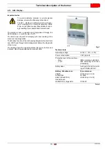
5.15
Electrical wiring
Notes on safety for the electrical wiring
5.15.1 Notes on terminals
Two types of terminals with "spring" system can be found on the
electrical panel. The opening of these terminals must be made
via a suitable tool, using a flat-blade screwdriver of the correct
size. The first type of terminal "A" (present on the "2000" burner)
is reserved for the connection of the three-phase line and has a
rotation type opening. The second type “B” has a pressure open-
ing system.
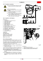
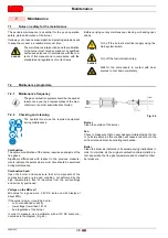
Type “A” terminal opening (Fig. 30)
Insert the correct screwdriver into the hole until it stops,
rotate anti-clockwise pushing down (the terminal can be kept
open by pressing the orange button).
Insert the previously stripped cable, turn the screwdriver
slightly and pull it out.
Make sure the cable is securely fastened Fig. 30.
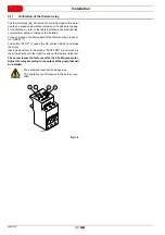
Type “B” terminal opening (Fig. 31)
insert the correct screwdriver into the opening, pushing
down until the hole for the cable is completely open.
Insert the previously stripped cable and remove the screw-
driver. Make sure the cable is securely fastened Fig. 31.
DANGER
The electrical wiring must be carried out with the electrical supply disconnected.
Electrical wiring must be made in accordance with the regulations currently in force in the country of destination
and by qualified personnel. Refer to the wiring diagrams.
The manufacturer declines all responsibility for modifications or connections different from those shown in the wir-
ing diagrams.
Check that the electrical supply of the burner corresponds to that shown on the identification label and in this man-
ual.
The burner has been type-approved for intermittent operation (FS1). This means that it should as a rule be
stopped at least once every 24 hours to enable the control box to perform checks of its own start-up efficiency.
Normally, burner stopping is guaranteed by the boiler's thermostat/pressure switch.
If this is not the case, a time switch should be fitted in series to TL to stop the burner at least once every 24 hours.
Refer to the wiring diagrams.
The burner is factory set for FS1 operation (1 stop every 24 hours); it can be converted to FS2 operation (continu-
ous - 1 stop every 72 hours), by changing the parameters using the menu of the AZL Display.
The electrical safety of the device is obtained only when it is correctly connected to an efficient earthing system,
made according to current standards. It is necessary to check this fundamental safety requirement. In the event of
doubt, have the electrical system checked by qualified personnel. Do not use the gas tubes as an earthing system
for electrical devices.
The electrical system must be suitable for the maximum power absorption of the device, as indicated on the label
and in the manual, checking in particular that the section of the cables is suitable for that level of power absorp-
tion.
For the main power supply of the device from the electricity mains:
- do not use adapters, multiple sockets or extensions;
- make provisions for an omnipolar switch with a gap between the contacts of at least 3 mm (over-voltage cate-
gory III), as required by current safety regulations.
Do not touch the device with wet or damp body parts and/or in bare feet.
Do not pull the electric cables.
Fig. 30
20114254
Fig. 31
20114253
Содержание RLS 1600/EV C11
Страница 2: ...Original instructions ...
Страница 48: ...20067636 46 GB Appendix Electrical panel layout 0 0 0 0 0 0 0 0 ...
Страница 49: ...47 20067636 GB Appendix Electrical panel layout ...
Страница 51: ...49 20067636 GB Appendix Electrical panel layout ...
Страница 52: ...20067636 50 GB Appendix Electrical panel layout 0 1 1 1 ...
Страница 53: ...51 20067636 GB Appendix Electrical panel layout 0 1 0 ...
Страница 54: ...20067636 52 GB Appendix Electrical panel layout 0 1 1 1 2 1 3 1 1 1 1 1 1 1 41 4 4 1 1 2 1 ...
Страница 55: ...53 20067636 GB Appendix Electrical panel layout 0 0 0 1 0 2 0 0 0 0 0 0 0 30 3 3 0 0 1 0 4 ...
Страница 56: ...20067636 54 GB Appendix Electrical panel layout 0 0 1 2 0 0 3 3 3 0 1 4 ...
Страница 60: ...20067636 58 GB Appendix Electrical panel layout ৼ 0 1 1 1 1 1 2 2 2 0 2 2 2 2 2 2 2 2 2 2 2 0 2 3 ...
Страница 62: ......
Страница 63: ......