


Maintenance
20153653
22
GB
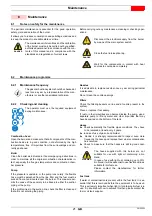
Cleaning the fan
Proceed as follows:
unscrew the screws 1)(Fig. 23) and take out the air damper
2);
loosen the screws 3) and take out the suction inlet 4);
clean the fan and the inside of the suction inlet, using a suit-
able brush and compressed air.
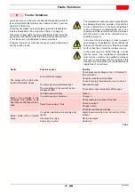
If necessary, carefully disassemble the fan (Fig. 24).
When reinstalling, follow the above indications in reverse order;
put all the burner components back in their original positions.
Air damper
Inside the suction casing 2)(Fig. 23) there is a damper that opens
due to the effect of the depression generated when operating.
The device interrupts the natural flow of air from the burner to the
boiler and vice-versa during stop phases.
It is important to periodically check the device and clean if there
are accumulations of dust that can obstruct the regular opening
and closing of the damper.
Combustion
Carry out an analysis of the combustion flue gases.
Significant differences with respect to the previous measure-
ments indicate the points where most care should be exercised
during maintenance.
In case the combustion values found at the beginning of the inter-
vention do not respect the standards in force or, in any case, do
not correspond to a proper combustion, contact the Technical As-
sistant in order to carry out the necessary adjustments.
Let the burner run at full capacity for about ten minutes, setting all
the elements correctly as explained in this manual.
Then carry out the analysis of the combustion by checking:
•
Smoke temperature at the flue;
•
CO2 content (%);
•
CO content (ppm);
•
Smoke value according to opacity smokes index according to
Bacharach scale.
Tab. H
8.2.3
Safety components
The safety components must be replaced at the end of their life
cycle indicated in Tab. I. The specified life cycles do not refer to
the warranty terms indicated in the delivery or payment
conditions.
Tab. I
WARNING
Check to make sure that no dust has accumulated
inside the fan or on its blades, as this condition will
cause a reduction in the air flow rate and provoke
polluting combustion.
When performing these operations, take care not
to damage the fan.
WARNING
It is essential to respect position B)(Fig. 24), indi-
cated in the table.
3
2
1
4
Fig. 23
20110526
Model
B
All models
51 ± 0.2mm
Safety component
Life cycle
Flame control
10 years or 250,000
operation cycles
Flame sensor
10 years or 250,000
operation cycles
Gas valves (solenoid)
10 years or 250,000
operation cycles
Pressure switches
10 years or 250,000
operation cycles
Pressure adjuster
15 years
Servomotor (electronic
cam) (if present)
10 years or 250,000
operation cycles
Oil valve (solenoid) (if
present)
10 years or 250,000
operation cycles
Oil regulator (if present)
10 years or 250,000
operation cycles
Oil pipes/ couplings
(metallic) (if present)
10 years
Flexible hoses (if present)
5 years or 30,000 pressurised
cycles
Fan impeller
10 years or 500,000 start-ups
B
3
Fig. 24
D9922
Fan