27
20170350
GB
Start-up, calibration and operation of the burner
7.5
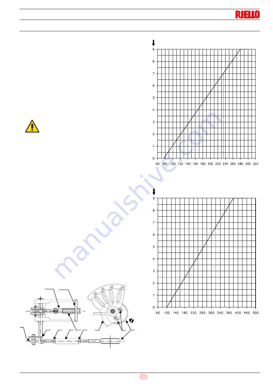
Combustion head adjustment
The combustion head moves at the same time of the eccentric 8),
(Fig. 22) and variable profile cam 1) (Fig. 26).
The head positioning can be seen on cylinder 2) (Fig. 23).
The control levers of the head are set at the factory to the
maximum stroke of 45 mm. The graduated cylinder 2) moves
from notch 0 to notch 9), suitable for a modulation range of 75 ÷
300 kg/h.
To obtain a different modulation range, calibrate these levers
again so that the stroke of the head is as in the following diagram
(Fig. 25).
Example with PRESS 300 P/G burner:
for a modulation from 100 ÷ 235 kg/h, it is possible to detect from
the diagram: notch 1 at 100 kg/h, notch 7 at 235 kg/h, with a
stroke equal to 6 notches.
To change the stroke of the combustion head proceed as follows:
control connecting rod 1) of driving rod 8) of combustion head is
provided with a slot; by pulling the tie-rod 9) towards the outside
of the slot the stroke of the head shortens by up to approx. 20
mm.
If a more consistent reduction is needed, act as follows:
with servomotor at 0°, loosen the screws 5) and push, in the
arrow direction, the ring 6) placed under the variable profile cam
7). This allows obtaining a reduction of the eccentricity with a
consequent reduction of the stroke.
When finished, firmly tighten the screws 5).
The desired stroke of the combustion head is set with the above-
indicated calibrations. In the previous example (6 notches) the
start and end of the stroke must coincide with values 1 and 7. To
obtain this, rotate the hexagonal sleeve 3), in one direction or the
other, after loosening the nuts 4).
With servomotor set to 0° notch 1 must match with the reference
plane 10), while with servomotor set to 130° it must match with
notch 7. Once adjustment operations are completed, firmly lock
the nuts 4) with the ball joint 9) positioned as in the figure. Head
calibrations are performed with burner closed, not operating and
with released servomotor.
At the end of the adjustment, by allowing the cam 7) to perform a
few travels, check that between 0° and 130° there is no sticking
(Fig. 23).
ATTENTION
To prevent any sticking, do not exceed the
maximum and minimum opening positions
corresponding on cylinder 2) to notch 9 with
servomotor at 130° and notch 0 with servomotor
at 0°, respectively.
8
10
9
1
4
3
2
4
7
5
6
Fig. 23
D2581
Fig. 24
No. notches
Maximum light oil output
kg/h
Combu
stio
n head
stroke
D2706
PRESS 300 P/G
Fig. 25
No. notches
Maximum light oil output
kg/h
Combu
stio
n head
stroke
D2782
PRESS 450 P/G
Содержание P 300 P/G
Страница 2: ...Translation of the original instructions...
Страница 46: ...20170350 44 GB Appendix Electrical panel layout 0 1 2 0 3 4 1 1 1 1 1 5 6 6 6 7 6 8 6 6 6 6 6 6 6 6 6 6 7 6...
Страница 47: ...45 20170350 GB Appendix Electrical panel layout 0 0 0 1 2 3 4 0 50 0 6 6 7 8 9 7 7 7 A B B B...
Страница 48: ...20170350 46 GB Appendix Electrical panel layout 0 0 0 1 2 3 4 0 50 0 6 6 7 84 9 8 4 7 7 7 A B B B...
Страница 52: ...20170350 50 GB Appendix Electrical panel layout 0 1 1 0 0 2 2 2 2 3 45 6 6 3 45 7 8 6 7 8 9 9 8 1 8 4 4 2 0...
Страница 55: ......


