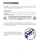
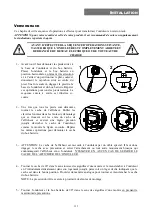
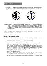
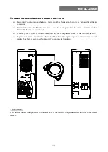
background image


146 


U

TILISATION


M

ODE DE FONCTIONNEMENT


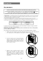
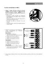
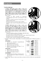
Le mode qui garantit le maximum de protection à la charge est le mode ON LINE (défaut) où l’énergie pour  
la charge subit une double conversion et où elle est reconstruite en sortie de manière parfaitement sinusoïdale 
avec une fréquence et une tension fixées par le contrôle numérique par microprocesseur indépendamment de 
l’entrée (V.F.I.). 

*


A part le mode traditionnel de fonctionnement ON LINE double conversion, il est possible de configurer les 
autres modes suivants: 


ECO (LINE INTERACTIVE) 


SMART (SMART ACTIVE) 


STBYOFF (STAND-BY OFF) 

 
Afin d’optimiser le rendement, en mode ECO la charge est normalement alimentée par bypass. Au cas où le 
réseau dépasserait les tolérances prévues, l’onduleur commute en fonctionnement ON LINE normal double  
conversion. Cinq minutes environ après que le réseau est rentré dans la tolérance, la charge est de nouveau 
commutée sur bypass. 
 
Dans  le  cas  où  l’utilisateur  ne  saurait  choisir  le  mode  de  fonctionnement  le  plus  approprié  (ON  LINE  ou 
ECO), il peut sélectionner le mode SMART ACTIVE dans lequel l’onduleur décide de manière autonome le 
mode de configuration en fonction d’une statistique relevée sur la qualité du réseau d’alimentation,. 
 
Enfin, le mode STAND-BY OFF permet d’obtenir un fonctionnement de secours: 
en présence du réseau la charge est coupée tandis qu’en cas de black-out la charge est alimentée sur onduleur 
par les batteries. 


R.E.P.O. 

Cette  entrée isolée  est utilisée  pour arrêter l’onduleur à distance en  cas  d’urgence.  L’éventuel  interrupteur 
normalement fermé de “Remote Emergency Power Off” (R.E.P.O.) doit être raccordé au connecteur présent 
à l’arrière de l’onduleur. 
L’onduleur sort de l’usine avec les bornes R.E.P.O. court-circuitées: éliminer le court-circuit si ce contact est 
raccordé au moyen d’un interrupteur d’urgence distant. 
 
Le  circuit  de  R.E.P.O.  est  auto-alimenté  par  des  circuits  de  type  SELV.  Aucune  tension  externe 
d’alimentation  n’est  donc  requise.  Quand  il  est  fermé  (condition  normale),  il  passe  un  courant  de  10mA 
maximum. 


P

RISE AUXILIAIRE PROGRAMMABLE 

(

POWER SHARE

L’onduleur est équipé d’une prise de sortie qui permet de débrancher automatiquement la charge qui y est 
appliquée  dans  certaines  conditions  de  fonctionnement.  Les  événements  qui  déterminent  le  déclenchement 
automatique  de  la  prise  de  Power  share  peuvent  être  sélectionnés  par  l’utilisateur  à  travers  le  logiciel  de 
configuration (voir paragraphes 

Logiciel de configuration

 et 

Configuration


onduleur

). 

Il est possible, par exemple, de sélectionner le déclenchement après un certain temps de fonctionnement sur 
batterie,  ou  dès  qu’est  atteint  le  seuil  de  pré-alarme  de  fin  de  décharge  des  batteries,  ou  encore  quand  un 
événement de surcharge se produit.  


*


La  valeur  rms  de  la  tension  de  sortie  est  fixée  par  le  contrôle  par  microprocesseur  indépendamment  de  la  tension 

d’entrée  tandis  que  la  fréquence  de  la  tension  de  sortie  est  synchronisée  (dans  une  tolérance  configurable  par 
l’utilisateur)  avec  celle  d’entrée  pour  permettre  l’utilisation  du  bypass.  Au-delà  de  cette  tolérance,  l’onduleur  se 
désynchronise et se place en fréquence nominale, le bypass n’est alors plus utilisable (free running mode). 

Содержание SENTINEL DUAL SDL 10000

Страница 1: ......

Страница 2: ......

Страница 3: ...EZZA 5 MANUALE D USO 15 GB SAFETY 6 USER S MANUAL 51 D SICHERHEIT 7 BEDIENUNGSANLEITUNG 87 F SÉCURITÉ 8 MANUEL D UTILISATEUR 123 E SEGURIDAD 9 MANUAL DE USUARIO 159 GR ΑΣΦΑΛΕΙΑ 10 S SÄKERHETEN 11 NL VEILIGHEID 12 P SEGURANÇA 13 ...

Страница 4: ...4 ...

Страница 5: ...rattate di conseguenza Non gettare i pacchi batterie sul fuoco possono esplodere Non tentare di aprire i pacchi batterie sono prive di manutenzione Inoltre l elettrolita è pericoloso per la pelle e per gli occhi e può risultare tossico f Non accendere l UPS se si nota una perdita di liquido o se si vede una polvere bianca residua g Evitare che acqua liquidi in genere e o altri oggetti estranei ent...

Страница 6: ...ks into fire they may explode Do not try to open the battery packs they do not require any maintenance Furthermore the electrolyte is dangerous if it comes into contact with the skin or the eyes and may be toxic f Do not switch the UPS on if there is any leak of liquid or if a residual white powder is noted g Do not allow water liquids in general and or other foreign bodies to get into the UPS h I...

Страница 7: ...ssen entsprechend entsorgt werden Die Batteriepakete nicht ins Feuer werfen sie können explodieren Nicht versuchen die Batteriepakete zu öffnen sie sind wartungsfrei Das Elektrolyt schadet Haut und Augen und kann zu Vergiftungen führen f Die USV nicht einschalten wenn Flüssigkeit austritt oder man weiße Pulverrückstände findet g Verhindern dass Wasser und oder ganz allgemein Flüssigkeiten und oder...

Страница 8: ...atteries dans le feu les batteries pourraient exploser Ne pas essayer d ouvrir les packs batteries ils ne nécessitent aucun entretien De plus l électrolyte est dangereux pour la peau et les yeux et il peut s avérer toxique f Ne pas mettre l ASI en marche en cas de perte de liquide ou en présence d une poudre blanche résiduelle g Eviter que de l eau des liquides en général et ou tout autre objet ét...

Страница 9: ...e correctamente No tire nunca los paquetes de baterías al fuego podrían explotar No intente abrir los paquetes de baterías éstos no requieren mantenimiento El electrolito puede dañar la piel y los ojos e incluso resultar tóxico f No encienda el SAI si detecta que una pérdida de líquido o si observa residuos de polvo blanco g Ha de evitarse que entren agua líquidos en general y o cuerpos extraños e...

Страница 10: ...ηάγεηε ηηο κπαηαξίεο ζε θσηηά κπνξεί λα εθξαγνύλ Με δνθηκάζεηε λα αλνίμεηε ηα παθέηα ζπζηνηρηώλ δελ ρξεηάδνληαη θακηά ζπληήξεζε Δμάιινπ ν ειεθηξνιύηεο είλαη επηθίλδπλνο αλ έιζεη ζ επαθή κε ην δέξκα ή ηα κάηηα θαη κπνξεί λα είλαη ηνμηθόο ζη Μελ αλάςεηε ην UPS αλ ππάξρεη θάπνηα δηαξξνή πγξνύ ή αλ παξαηεξεζεί ππόιεηκκα ιεπθήο ζθόλεο δ Μελ επηηξέςεηε λεξό ή γεληθώο πγξά θαη ή άιια μέλα ζώκαηα λα εηζρσ...

Страница 11: ... explodera Försök inte öppna batterierna de behöver inget underhåll Dessutom är syran farlig vid kontakt med hud eller ögon och kan vara giftig f Sätt inte på UPS enheten oavbrytbar strömförsörjning om det finns läckage av vätska eller om rester av vitt pulver konstateras g Tillåt inte att vatten vätskor i allmänhet och eller övriga främmande föremål kan komma in i UPS enheten oavbrytbar strömförs...

Страница 12: ...kunnen ontploffen Probeer de accu s nooit te openen ze vereisen absoluut geen onderhoud Bovendien is de elektrolyt gevaarlijk als deze in aanraking komt met de huid of de ogen De elektrolyt kan ook giftig zijn f De UPS niet aanschakelen wanneer zich deze lekt of wanneer u wit poeder opmerkt g Let erop dat geen water vloeistoffen in het algemeen en of vreemde voorwerpen in de UPS terecht raken h In...

Страница 13: ...ideradas LIXO TÓXICO e devem ser manejadas de tal maneira Não deixe as baterias entrarem em contacto com fogo elas são inflamáveis e podem explodir Não tente abrir as baterias elas não requerem manutenção À parte disso o electrólito liberado é nocivo à pele e aos olhos e pode ser tóxico f Não ligar o UPS caso observe uma perda de líquido ou note um pó residual branco g Evitar que água líquidos em ...

Страница 14: ...14 ...

Страница 15: ...15 I MANUALE D USO I ...

Страница 16: ...a vigente In questo prodotto non sono utilizzati materiali pericolosi quali CFC HCFC o amianto Nella valutazione degli imballi la scelta del materiale è stata fatta prediligendo materie riciclabili Per il corretto smaltimento si prega di separare e di identificare la tipologia di materiale costituente l imballo seguendo la tabella sottostante Smaltire ogni materiale secondo le normative vigenti ne...

Страница 17: ...NIMENTO DELL UPS 33 INDICAZIONI PANNELLO DISPLAY 34 Indicatori di stato dell UPS 34 Area visualizzazione misure 35 Versione monofase 35 Versione trifase 36 Area di configurazione 37 MODALITÀ DI FUNZIONAMENTO 38 R E P O 38 PRESA AUSILIARIA PROGRAMMABILE POWER SHARE 38 CONFIGURAZIONE UPS 39 PORTE DI COMUNICAZIONE 41 Connettori RS232 e USB 41 Communication Slot 41 SOFTWARE 42 Software di monitoraggio...

Страница 18: ...e rack Ecco come si presenta il prodotto nelle 2 differenti versioni SDL 6500 TM SDL 8000 SDL 8000 TM SDL 10000 SDL 10000 TM Potenza nominale VA 6500 8000 10000 Tensione nominale Vac 220 230 240 Dimensioni H x L x P mm 2 x 455 x 175 x 660 1 Peso Kg 28 63 circa 29 65 circa 30 65 circa 1 Nella versione rack con maniglie installate la dimensione H è diversa 483mm x 175mm x 660mm H x L x P Nota 175mm ...

Страница 19: ...terruttore generale Pannello frontale rimuovibile Vista posteriore Connettore espansione batteria Ventola di raffreddamento Porta di comunicazione RS232 Porta di comunicazione USB Ventola di raffreddamento Prese IEC 10 A Power share Cassetto connessioni IN OUT Protezione termica prese Power share Slot di espansione COMUNICATION SLOT Remote emergency power off R E P O ...

Страница 20: ...ONE VISTE BATTERY BOX Vista posteriore Feritoie di sgancio Maschera estraibile ruotabile Pannello frontale rimuovibile Griglia di aerazione Sezionatori portafusibili Connettori per espansione batterie Vista frontale ...

Страница 21: ...zione 2 Funzionamento da rete 8 Richiesta manutenzione 3 Funzionamento da batteria 9 Timer 4 Carico alimentato da bypass 10 Area visualizzazione misure 5 Indicatore autonomia batteria 11 Stand by allarme 6 Indicatore livello carico Display LCD Pulsante ON Pulsante SEL SET Pulsante STBY ...

Страница 22: ... per prima cosa procedere alla verifica del contenuto L imballo dovrà contenere UPS Battery box 1 passacavo 2 blocca guaina 6 cover in plastica pannelli superiori UPS e Battery box Puntali per connessione cavi morsettiera 2 chiavette in plastica er sgancio display 2 Kit maniglie Cavo seriale RS232 ...

Страница 23: ...23 INSTALLAZIONE Cavo di connessione UPS Battery box 2 Fusibili per Battery box 14x51 mm 50A 400V Manuale utente CD ROM software User s manual ...

Страница 24: ...FETTUARE LA SEGUENTE SEQUENZA DI OPERAZIONI ASSICURARSI CHE L UPS SIA COMPLETAMENTE SPENTO E PRIVO DI COLLEGAMENTO ALLA RETE ELETTRICA E A QUALSIASI CARICO Una volta estratti dagli imballi l UPS e il Battery box si presentano già predisposti per l installazione in configurazione tower Per completare tale configurazione basta montare le sei cover in plastica in dotazione tre nella parte superiore d...

Страница 25: ...ti tutti i piedini si deve procedere a ruotare le maschera display Infilare le chiavette in dotazione nelle feritoie di sgancio che si trovano ai lati della maschera display ed esercitare una leggera pressione quanto basta per sganciare la maschera dall UPS come evidenziato nella figura a lato Ripetere le stesso operazioni per sganciare la maschera dal Battery box 3 ATTENZIONE La maschera display ...

Страница 26: ...x avere cura di seguire le seguenti note Installare l UPS e il Battery box su di una superficie piana e stabile Evitare il posizionamento in luoghi esposti alla luce diretta del sole o ad aria calda Mantenere la temperatura ambiente tra 0 C e 40 C N B l UPS è in grado di funzionare con una temperatura ambiente compresa tra 0 C e 40 C La temperatura ottimale di funzionamento delle batterie poste al...

Страница 27: ...l retro del Battery box Chiudere i sezionatori Il cavo può essere collegato indifferentemente ad una delle due prese presenti sul retro del Battery box La presa d espansione che rimane inutilizzata sul retro del Battery box è una predisposizione per il collegamento in cascata di ulteriori Battery box per aumentare l autonomia dell UPS ATTENZIONE Non è ammesso collegare più di un UPS per ogni Batte...

Страница 28: ...e Tipo B o Tipo A Trifase Tipo B Il regime di neutro viene modificato solo se è presente un trasformatore di isolamento o quando l UPS funziona con neutro sezionato a monte Evitare comunque di collegare il neutro di uscita a quello di ingresso o a terra perchè questa operazione potrebbe danneggiare l UPS Per effettuare i collegamenti di rete e carico seguire le indicazioni sottostanti 1 Installare...

Страница 29: ...one 2 Collegare i fili ai relativi morsetti seguendo scrupolosamente le indicazioni riportate qui di seguito Linea di ingresso a Assicurarsi che il magnetotermico a monte sia aperto b Collegare il filo di terra al morsetto 3 c Collegare il filo di neutro al morsetto 1 d Collegare il filo della fase al morsetto 2 Linea di uscita a Collegare il filo di terra al morsetto 6 b Collegare il filo di neut...

Страница 30: ...e 3 cavi con sezione 6 mm2 TERRA N e L Facendo riferimento alla figura qui a fianco Inserire i cavi provenienti dal magnetotermico da 63A all interno del blocca guaina P2 linea di ingresso Inserire i cavi provenienti dal carico all interno del blocca guaina P1 linea di uscita Spellare i cavi rispettando la misura indicata Inserire la parte appena spellata nei puntali in dotazione 2 Collegare i fil...

Страница 31: ...2 Per fare il collegamento con i morsetti di Bypass remoto utilizzare un cavo 2x0 75 mm2 Facendo riferimento alla figura qui a fianco Inserire il cavo di comando esterno di Bypass all interno del passacavo P3 Spellare i cavi rispettando la misura indicata Inserire la parte appena spellata nei puntali in dotazione 3 Collegare i fili ai relativi morsetti seguendo le istruzioni precedentemente spiega...

Страница 32: ...APPORRE UN ETICHETTA DI AVVERTIMENTO SU TUTTI I SEZIONATORI DELLA POTENZA DI RETE INSTALLATI LONTANO DALL AREA DELL UPS ALLO SCOPO DI RICHIAMARE IL PERSONALE DI ASSISTENZA SUL FATTO CHE IL CIRCUITO É COLLEGATO AD UN UPS L ETICHETTA DEVE RIPORTARE IL TESTO SEGUENTE ISOLARE IL SISTEMA DI CONTINUITÀ UPS PRIMA DI OPERARE SU QUESTO CIRCUITO ...

Страница 33: ... icona sul display e si deve udire un beep ogni 4 secondi 3 Richiudendo l interrutore a monte l UPS deve ritornare a funzionare da rete ACCENSIONE DA BATTERIA 1 Premere l interruttore generale posto sul pannello frontale 2 Tenere premuto il pulsante ON per almeno 5 secondi Tutte le icone del display si accendono per 1 secondo e l UPS emette un beep 3 Accendere le apparecchiature collegate all UPS ...

Страница 34: ...è sincronizzata con la tensione di rete Fissa L UPS sta funzionando da batteria Quando si trova in questo stato l UPS emette un segnale acustico beep ad intervalli regolari di 4 sec Lampeggiante Preallarme di fine scarica Indica che l autonomia delle batterie sta terminando In questa condizione l UPS emette un beep ad intervalli regolari di 1 sec Fissa Indica che i carichi collegati all UPS sono a...

Страница 35: ...ortati alcuni esempi 1 I valori riportati nelle immagini in tabella sono puramente indicativi 2 I codici di FAULT LOCK possono essere visualizzati solo se al momento attivi presenza di un anomalia allarme o di un blocco ESEMPIO GRAFICO 1 DESCRIZIONE Tensione di rete Frequenza di rete Tensione in uscita dall UPS Frequenza della tensione di uscita Autonomia residua delle batterie Percentuale di cari...

Страница 36: ...ESEMPIO GRAFICO 1 DESCRIZIONE Tensione fase 1 2 Tensione fase 2 2 Tensione fase 3 2 Frequenza della tensione di uscita Autonomia residua delle batterie ESEMPIO GRAFICO 1 DESCRIZIONE Percentuale di carica delle batterie Tensione totale delle batterie Percentuale del carico applicato Corrente assorbita dal carico Temperatura del sistema di raffreddamento della elettronica interna all UPS Anomalia Al...

Страница 37: ...no 2 sec La scritta SET si accende e compare una freccia alla sinistra di Frequenza La freccia indica il settaggio selezionato Per cambiare la selezione del parametro da modificare premere il pulsante SEL SET Per modificare la voce selezionata premere il pulsante ON Per uscire dall area di configurazione tener premuto il pulsante SEL SET per almeno 2 sec SETTAGGI POSSIBILI Frequenza 50 Hz 60 Hz Sp...

Страница 38: ...spegnere l UPS a distanza in caso di emergenza L eventuale interruttore normalmente chiuso di Remote Emergency Power Off R E P O deve essere collegato al connettore presente sul retro dell UPS L UPS viene fornito dalla fabbrica con i morsetti R E P O cortocircuitati rimuovere il cortocircuito se tale contatto è collegato all ausiliario di un interruttore remoto di emergenza Il circuito di R E P O ...

Страница 39: ...scita 230V 220V 230V 240V 220 240 in step di 1V solo tramite software Modalità di funzionamento Selezione di una delle 4 diverse modalità di funzionamento ON LINE ON LINE ECO SMART ACTIVE STAND BY OFF Ritardo di accensione Tempo di attesa per la riaccensione automatica dopo il ritorno della rete 5 sec Disabilitato 1 255 in step di 1 sec Spegnimento per carico minimo Spegnimento automatico dell UPS...

Страница 40: ...so per il passaggio su bypass e per la sincronizzazione dell uscita 5 0 25 0 5 0 75 1 10 in step di 1 Soglie di tensione bypass Seleziona il range di tensione ammesso per il passaggio su bypass Bassa 180V Alta 264V Bassa 180 200 in step di 1V Alta 250 264 in step di 1V Soglie di tensione bypass per ECO Seleziona il range di tensione ammesso per il funzionamento in modalità ECO Bassa 200V Alta 253V...

Страница 41: ... 4 GND 5 GND 6 7 Ingresso di alimentazione interfaccia 12Vdc 8 Contatto chiuso preallarme di fine scarica 9 Contatto chiuso funzionamento da batteria Contatto optoisolato max 30Vdc 10mA Communication Slot l UPS è fornito di uno slot di espansione per schede di comunicazione opzionali vedi figura a lato che consentono all apparecchiatura di dialogare utilizzando i principali standard di comunicazio...

Страница 42: ...OM del PC tramite il cavo seriale in dotazione oppure collegare la porta USB dell UPS ad una porta USB del PC utilizzando un cavo standard USB Scaricare il software dal sito web www riello ups com selezionando il sistema operativo desiderato Seguire le istruzioni del programma di installazione Per informazioni più dettagliate sull installazione ed utilizzo consultare il manuale del software scaric...

Страница 43: ...sto ON posto sul pannello frontale per alimentare i carichi LA MODALITA STAND BY OFF E SELEZIONATA E necessario cambiare la modalità Infatti la modalità STAND BY OFF soccorritore alimenta i carichi solo in caso di black out MANCA IL COLLEGAMENTO AL CARICO Verificare il collegamento al carico L UPS FUNZIONA DA BATTERIA NONOSTANTE SIA PRESENTE LA TENSIONE DI RETE INTERVENTO DELLA PROTEZIONE A MONTE ...

Страница 44: ...ntare il carico spegnere e riaccendere l UPS nel caso il problema si ripresentasse chiamare il centro assistenza IL CICALINO SUONA IN MODO CONTINUO ED IL DISPLAY SEGNALA UNO TRA I CODICI F04 L04 LA TEMPERATURA DEI DISSIPATORI INTERNI DELL UPS E TROPPO ELEVATA Verificare che la temperatura dell ambiente in cui si trova l UPS non superi i 40 C IL CICALINO SUONA IN MODO CONTINUO ED IL DISPLAY SEGNALA...

Страница 45: ...lè di ingresso bloccato non apre A54 Carico della soglia utente impostata A61 Batterie da sostituire A62 Battery box assente o non collegato A63 Attesa ricarica batterie Allarmi sono problemi più critici rispetto alle anomalie perché il loro perdurare può provocare anche in un tempo molto breve il blocco dell UPS CODICE DESCRIZIONE F03 Alimentazione ausiliaria non corretta F04 Sovratemperatura dis...

Страница 46: ...cchi da sovraccarico forti e persistenti e per il blocco per corto circuito CODICE DESCRIZIONE L03 Alimentazione ausiliaria non corretta L04 Sovratemperatura dissipatori L05 Sensore1 di temperatura guasto L06 Sensore3 di temperatura guasto L07 Sensore2 di temperatura guasto L10 Fusibile di ingresso rotto o relè di ingresso bloccato non chiude L13 Precarica condensatori fallita L20 Sottotensione ba...

Страница 47: ...inale in VA 8000 10000 Potenza nominale in W 7200 9000 Corrente di cortocircuito 1 5 x In per t 0 5sec VARIE Corrente di fuga verso terra 10mA Rendimento AC AC 92 Temperatura ambiente 6 0 40 C Umidità 90 senza condensa Protezioni eccessiva scarica delle batterie sovracorrente cortocircuito sovratensione sottotensione termica Hold up time 30msec Rumorosità 45dB A a 1mt Dimensioni H x L x P mm 2 x 4...

Страница 48: ... 1 Potenza nominale in VA 6500 8000 10000 Potenza nominale in W 5850 7200 9000 Corrente di cortocircuito 1 5 x In per t 0 5sec VARIE Corrente di fuga verso terra 10mA Rendimento AC AC 92 Temperatura ambiente 6 0 40 C Umidità 90 senza condensa Protezioni eccessiva scarica delle batterie sovracorrente cortocircuito sovratensione sottotensione termica Hold up time 40msec Rumorosità 45dB A a 1mt Dimen...

Страница 49: ...ezioni sovracorrente cortocircuito Dimensioni H x L x P mm 455 x 175 x 660 Peso Kg 63 65 1 20 25 C per una maggior vita delle batterie TABELLA TEMPI DI SOVRACCARICO TEMPI DI SOVRACCARICO FUNZIONAMENTO DA BYPASS INVERTER 100 Load 125 Attiva bypass dopo 2 sec In blocco dopo 120 sec In blocco dopo 60 sec 125 Load 150 Attiva bypass dopo 2 sec In blocco dopo 4 sec In blocco dopo 4 sec Load 150 Attiva b...

Страница 50: ...50 ...

Страница 51: ...51 GB USER MANUAL GB ...

Страница 52: ...rdous materials such as CFC HCFC or asbestos are used in this product When evaluating packaging the choice of material has been made favouring recyclable materials For correct disposal please separate and identify the type of material of which the packaging is made in the table below Dispose of all material in compliance with standards in force in the country in which the product is used Descripti...

Страница 53: ...TTERY 69 UPS SHUTDOWN 69 DISPLAY PANEL INDICATIONS 70 UPS status indicators 70 Measurements display area 71 Single phase version 71 Three phase version 72 Configuration area 73 OPERATING MODES 74 R E P O 74 PROGRAMMABLE AUXILIARY SOCKET POWER SHARE 74 UPS CONFIGURATION 75 COMMUNICATION PORTS 77 RS232 and USB connectors 77 Communication Slot 77 SOFTWARE 78 Monitoring and control software 78 Configu...

Страница 54: ... The 2 different versions of the product are shown below SDL 6500 TM SDL 8000 SDL 8000 TM SDL 10000 SDL 10000 TM Nominal power VA 6500 8000 10000 Nominal voltage Vac 220 230 240 Dimensions H x L x D mm 2 x 455 x 175 x 660 1 Weight Kg approx 28 63 approx 29 65 approx 30 65 1 The H dimension is different in the rack version with handles mounted 483mm x 175mm x 660mm H x L x D Note 175mm 4U 483mm 19 ...

Страница 55: ...ble display mask General switch Removable front panel Rear view Battery expansion connector Cooling fan RS232 communication port USB communication port Cooling fan IEC 10 A Power share sockets IN OUT connections drawer Power share sockets thermal protection COMMUNICATION expansion slot Remote emergency power off R E P O ...

Страница 56: ...6 PRESENTATION BATTERY BOX VIEWS Rear view Release slots Extractable rotatable mask Removable front panel Ventilation grille Fuse holder disconnecting switches Connectors for battery expansion Front view ...

Страница 57: ...ion area 2 Operation from mains 8 Maintenance request 3 Operation from battery 9 Timer 4 Load powered by the bypass 10 Measurement display area 5 Battery back up time indicator 11 Stand by alarm 6 Load level indicator LCD Display ON button SEL SET button STBY button ...

Страница 58: ...packaging first check the contents The packaging should contain the following UPS Battery box 1 cable guide 2 seal stops 6 plastic covers upper panels UPS and Battery box Ferrules for cables terminal board connection 2 plastic keys to release display 2 Handles kits RS232 serial cable ...

Страница 59: ...59 INSTALLATION UPS Battery box connection cable 2 Fuses for Battery box 14x51 mm 50A 400V User manual CD ROM software User s manual ...

Страница 60: ...RYING OUT THE FOLLOWING SEQUENCE OF OPERATIONS ENSURE THAT THE UPS IS COMPLETELY SWITCHED OFF AND NOT CONNECTED TO THE ELECTRICITY MAINS OR TO ANY LOAD Once removed from the packaging the UPS and the Battery box are ready for installation in a tower configuration All that is needed to complete this configuration is to mount the six plastic covers provided three in the upper part of the UPS and the...

Страница 61: ...is shown at the side 2 Once all the feet have been removed the display mask must then be rotated Insert the keys provided in the release slots located at the sides of the display mask and exert enough gentle pressure to release the mask from the UPS as shown in the figure at the side Repeat the same operations to release the mask from the Battery box 3 WARNING The display mask is connected to the ...

Страница 62: ...o the Battery box ensure compliance with the following points Install the UPS and the Battery box on a flat stable surface Avoid placing in positions exposed to direct sunlight or hot air Maintain room temperature between 0 C and 40 C N B the UPS can operate with an ambient temperature of between 0 C and 40 C The optimal operating temperature for the batteries inside the Battery box is between 20 ...

Страница 63: ...at the back of the Battery box Close the disconnecting switches The cable can be connected to either of the two sockets located at the back of the Battery box The remaining unused expansion socket at the back of the Battery box can be used for the cascade connection of further Battery boxes to increase UPS autonomy WARNING Only one UPS can be connected for each Battery box or for several cascade c...

Страница 64: ...Differential switch Single phase Type B or Type A Three phase Type B The neutral arrangements will only be changed if an isolation transformer is connected or when the UPS is operating with the neutral isolated upstream Avoid connecting the output neutral to the input neutral or to earth as this could damage the UPS For the mains and load connections follow the instructions below 1 Install a 63A m...

Страница 65: ...rrules provided 2 Connect the wires to the relative terminals strictly following the instructions set out below Input line a Ensure that the magneto thermal switch upstream is open b Connect the earth wire to terminal 3 c Connect the neutral wire to terminal 1 d Connect the phase wire to terminal 2 Output line a Connect the earth wire to terminal 6 b Connect the neutral wire to terminal 7 c Connec...

Страница 66: ...nt For the output use 3 cables with 6 mm2 section EARTH N and L With reference to the figure shown at the side Insert the cables from the 63A magneto thermal switch into seal stop P2 input line Insert the cables from the load into seal stop P1 output line Strip the cables observing the measurements provided Insert the part that has just been stripped into the ferrules provided 2 Connect the wires ...

Страница 67: ...0 75 mm2 cable for connection with the remote Bypass terminals With reference to the figure shown at the side Insert the Bypass external control cable to the inside of cable guide P3 Strip the cables observing the measurements provided Insert the part that has just been stripped into the ferrules provided 3 Connect the wires to the relative terminals strictly following the instructions described a...

Страница 68: ... previously A WARNING LABEL MUST BE AFFIXED TO ALL MAINS POWER ISOLATING SWITCHES INSTALLED FAR FROM THE UPS AREA IN ORDER TO REMIND SUPPORT SERVICE PERSONNEL THAT THE CIRCUIT IS CONNECTED TO A UPS THE LABEL MUST CARRY THE FOLLOWING MESSAGE ISOLATE THE UNINTERRUPTIBLE POWER SYSTEM UPS BEFORE WORKING ON THIS CIRCUIT ...

Страница 69: ...be heard every 4 seconds 3 If the switch upstream is closed again the UPS must go back to operating from the mains START UP FROM BATTERY 1 Press the general switch located on the front panel 2 Keep the ON button pressed for at least 5 seconds All the icons on the display will light up for 1 second and the UPS will emit a beep 3 Switch on the equipment connected to the UPS UPS SHUTDOWN To switch th...

Страница 70: ...tant The UPS is operating from the battery When it is in this state the UPS emits an acoustic signal beep at regular intervals of 4 sec Flashing End of discharge prealarm Indicates that the battery back up time is coming to an end In this condition the UPS emits a beep at regular intervals of 1 sec Constant Indicates that the loads connected to the UPS are powered from the bypass Dynamic Indicates...

Страница 71: ...ersion Some examples are shown below 1 The values shown in the images in the table are purely indicative 2 The FAULT LOCK codes can only be displayed if they are active i e if there is a fault alarm or a lock GRAPHIC EXAMPLE 1 DESCRIPTION Mains voltage Mains frequency Voltage output from the UPS Output voltage frequency Residual battery back up time Percentage of battery charge GRAPHIC EXAMPLE 1 D...

Страница 72: ... alarm or a lock GRAPHIC EXAMPLE 1 DESCRIPTION Voltage phase 1 2 Voltage phase 2 2 Voltage phase 3 2 Output voltage frequency Residual battery back up time GRAPHIC EXAMPLE 1 DESCRIPTION Percentage of battery charge Total battery voltage Percentage of the applied load Current absorbed by the load Temperature of the cooling system for the UPS internal electronics Fault Alarm 3 the corresponding code...

Страница 73: ... least 2 sec The word SET will light up and an arrow will appear to the left of Frequency The arrow shows the selected setting To select a different parameter press the SEL SET button To change the selected item press the ON button To exit from the configuration area hold the SEL SET button down for at least 2 sec POSSIBLE SETTINGS Frequency 50 Hz 60 Hz Off frequency auto sensing Voltage 220 V 230...

Страница 74: ...tely switch off the UPS in an emergency Any Remote Emergency Power Off R E P O switch that is normally closed must be connected to the connector located at the back of the UPS The UPS is supplied ex works with the R E P O terminals short circuited remove the short circuit if this contact is connected to the auxiliary of a remote emergency switch The R E P O circuit is self powered with SELV type c...

Страница 75: ...utput voltage 230V 220V 230V 240V 220 240 in 1V steps only via software Operating mode To select one of the 4 different operating modes ON LINE ON LINE ECO SMART ACTIVE STAND BY OFF Start up delay Delay before automatic restart after the mains returns 5 sec Disabled 1 255 in 1 sec steps Shutdown due to minimum load Automatic shutdown of the UPS in operation from the battery if the load is less tha...

Страница 76: ...frequency range for the passage onto bypass and for synchronization of the output 5 0 25 0 5 0 75 1 10 in 1 steps Bypass voltage thresholds Selects the allowed voltage range for the passage onto bypass Low 180V High 264V Low 180 200 in 1V steps High 250 264 in 1V steps Bypass voltage thresholds for ECO Selects the allowed voltage range for operation in ECO mode Low 200V High 253V Low 180 220 in 1V...

Страница 77: ... 3 D 4 4 GND 5 GND 6 7 Interface power supply input 12Vdc 8 Contact closed end of discharge prealarm 9 Contact closed operation from battery Optoisolated contact max 30Vdc 10mA Communication Slot The UPS is provided with an expansion slot for optional communication cards see figure at the side which enable the device to dialog using the main communication standards Some examples Second RS232 port ...

Страница 78: ...COM communication port on the PC by means of the serial cable provided or connect the USB port on the UPS to a USB port on the PC using a USB standard cable Download the software from www riello ups com selecting the desired operating system Follow the installation program instructions For more detailed information about installation and use refer to the software manual which can be downloaded fro...

Страница 79: ... on the front panel to power the loads STAND BY OFF MODE HAS BEEN SELECTED The mode has to be changed The STAND BY OFF mode back up in fact only powers the loads in the event of a blackout NO CONNECTION TO THE LOAD Check the connection to the load THE UPS IS OPERATING FROM BATTERY EVEN THOUGH THE MAINS VOLTAGE IS PRESENT UPSTREAM PROTECTION TRIGGERED Reset the protection WARNING Check that there i...

Страница 80: ...ad switch the UPS off and then on again if the problem should occur again contact the support service centre THE BUZZER SOUNDS CONTINUOUSLY AND THE DISPLAY SHOWS ONE OF THESE CODES F04 L04 THE TEMPERATURE OF THE DISSIPATORS INSIDE THE UPS IS TOO HIGH Check that the temperature of the environment where the UPS is located does not exceed 40 C THE BUZZER SOUNDS CONTINUOUSLY AND THE DISPLAY SHOWS ONE ...

Страница 81: ...oes not open A54 Load preset user threshhold A61 Batteries to be replaced A62 No Battery box or not connected A63 Waiting to recharge batteries Alarms these are more critical problems than faults since if they persist even for a very short time they may cause the UPS to stop CODE DESCRIPTION F03 Auxiliary power supply not correct F04 Dissipators overtemperature F05 Temperature sensor1 faulty F07 T...

Страница 82: ...cks from strong and persistent overloads or locks due to short circuits CODE DESCRIPTION L03 Auxiliary power supply not correct L04 Dissipators overtemperature L05 Temperature sensor1 faulty L06 Temperature sensor3 faulty L07 Temperature sensor2 faulty L10 Input fuse broken or input relay locked does not close L13 Condenser precharge failed L20 Condenser bank undervoltage L21 Condenser bank overvo...

Страница 83: ...l power VA 8000 10000 Nominal power W 7200 9000 Short circuit current 1 5 x In for t 0 5sec SUNDRY Leakage current to earth 10mA AC AC performance 92 Ambient temperature 6 0 40 C Humidity 90 non condensing Protections excessive battery discharge overcurrent short circuit overvoltage undervoltage thermal Hold up time 30msec Noise 45 dB A at 1mt Dimensions H x L x D mm 2 x 455mm 19 x 175mm 4U x 660m...

Страница 84: ...actor 3 1 Nominal power VA 6500 8000 10000 Nominal power W 5850 7200 9000 Short circuit current 1 5 x In for t 0 5sec SUNDRY Leakage current to earth 10mA AC AC performance 92 Ambient temperature 6 0 40 C Humidity 90 non condensing Protections excessive battery discharge overcurrent short circuit overvoltage undervoltage thermal Hold up time 40msec Noise 45 dB A at 1mt Dimensions H x L x D mm 2 x ...

Страница 85: ...90 non condensing Protections overcurrent short circuit Dimensions H x L x D mm 455 x 175 x 660 Weight Kg 63 65 1 20 25 C for extended battery life TABLE OF OVERLOAD TIMES OVERLOAD TIMES OPERATION FROM BYPASS INVERTER 100 Load 125 Bypass active after 2 sec Locked after 120 sec Locked after 60 sec 125 Load 150 Bypass active after 2 sec Locked after 4 sec Locked after 4 sec Load 150 Bypass active in...

Страница 86: ...86 ...

Страница 87: ...87 D BEDIENUNGSANLEITUNG D ...

Страница 88: ...des vorliegenden Produkts keinerlei gefährlichen Materialien wie CFC HCFC oder Asbest verwendet Zur Verpackung wurden recyclebare Materialien verwendet Zur ordnungsgemäßen Entsorgung müssen die verschiedenen Materialien der Verpackung getrennt werden wobei die unten folgende Tabelle zu Hilfe genommen werden kann Die jeweiligen Materialien sind strikt nach den geltenden Bestimmungen des Landes in d...

Страница 89: ...TERIESTROM 105 ABSCHALTEN DER USV 105 ANZEIGEN AM DISPLAY 106 Anzeigen des USV Status 106 Bereich Messwert Anzeige 107 Version einphasig 107 Version dreiphasig 108 Konfigurations Bereich 109 BETRIEBSMODUS 110 R E P O 110 PROGRAMMIERBARER ZUSATZSTECKER POWER SHARE 110 USV KONFIGURATION 111 COMPUTER SCHNITTSTELLEN 113 Anschlüsse RS232 und USB 113 Communication Slot 113 SOFTWARE 114 Überwachungs und ...

Страница 90: ...tellt sich das Produkt in seinen zwei unterschiedlichen Versionen dar SDL 6500 TM SDL 8000 SDL 8000 TM SDL 10000 SDL 10000 TM Nennleistung VA 6500 8000 10000 Nennspannung Vac 220 230 240 Abmessungen H x B x T mm 2 x 455 x 175 x 660 1 Gewicht Kg 28 63 ungefähr 29 65 ungefähr 30 65 ungefähr 1 In der Version Rack mit installierten Griffen ist die Abmessung H anders 483mm x 175mm x 660mm H x B x T Anm...

Страница 91: ...Drehbare Display Maske Haupt schalter Abnehmbares Frontpaneel Rückansicht Anschluss Batterie Erweiterung Kühlgebläse Schnittstelle RS232 Schnittstelle USB Kühlgebläse Stecker IEC 10 A Power share Anschlussgehäuse IN OUT Stecker Thermoschutz Power share Erweiterungs Steckplatz COMUNICATION SLOT Remote emergency power off R E P O ...

Страница 92: ...RSTELLUNG ANSICHTEN DER BATTERY BOX Rückansicht Aushakschlitze Herausziehbare drehbare Maske Abnehmbares Frontpaneel Lüftungsrost Trennschalter Sicherungshalter Anschlüsse Batterie Erweiterung Vorderansicht ...

Страница 93: ...figurations Bereich 2 Netzbetrieb 8 Anforderung Wartung 3 Batteriebetrieb 9 Timer 4 Last Stromversorgung über Bypass 10 Bereich Messwert Anzeige 5 Anzeige Batterie Autonomie 11 Stand By Alarm 6 Anzeige Ladezustand LCD Display ON Taste SEL SET Taste STBY Taste ...

Страница 94: ... als erstes der Inhalt geprüft werden Die Verpackung muss folgendes enthalten USV Battery box 1 Kabelführung 2 Schutzhüllensperre 6 Plastikabdeckungen Obere Paneele USV und Battery Box Spitzen für Anschluss Kabel Klemme 2 Plastikkeile zum Aushaken des Display 2 Sätze Handgriffe Serielles Kabel RS232 ...

Страница 95: ...95 INSTALLATION Verbindungskabel USV Battery Box 2 Sicherungen für Battery Box 14x51 mm 50A 400V Bedienungsanleitung CD ROM Software User s manual ...

Страница 96: ...OR AUSFÜHRUNG DER NACHFOLGENDEN ARBEITSSCHRITTE SICHERSTELLEN DASS DIE USV VOLLSTÄNDIG AUSGESCHALTET IST UND WEDER AN DAS STROMNETZ NOCH AN LASTEN ANGESCHLOSSEN IST Nach dem Auspacken sind die USV und die Battery Box bereits für die Installation in der Tower Konfiguration vorbereitet Für die Vervollständigung dieser Konfiguration reicht es aus die sechs Plastikabdeckungen aus dem Lieferumfang zu m...

Страница 97: ...ie genau Abfolge dargestellt 2 Nach dem Ausbau der Stellfüße muss die Displaymaske gedreht werden Die Plastikkeile aus dem Lieferumfang in die Schlitze seitlich an der Display Maske einführen und anschließend leicht solange drücken bis die Maske von der USV ausgehakt ist Siehe nebenstehende Abbildung Die gleichen Arbeitsschritte zum Aushaken der Maske an der Battery Box wiederholen 3 ACHTUNG Die D...

Страница 98: ...ie USV und die Battery Box auf einer ebenen und stabilen Oberfläche installieren Einen Aufstellungsort mit direkter Sonnen oder Warmlufteinstrahlung vermeiden Die Raumtemperatur muss zwischen 0 C und 40 C gehalten werden Anmerkung Die USV kann bei einer Raumtemperatur zwischen 0 C und 40 C arbeiten Die optimale Betriebstemperatur der Batterien in der Battery Box liegt zwischen 20 C und 25 C Beträg...

Страница 99: ...kseite der Battery Box einsetzen Die Trennschalter schließen Das Kabel kann beliebig an einen der beiden Stecker auf der Rückseite der Battery Box angeschlossen werden Der unbenutzte Ausbaustecker auf der Rückseite der Battery Box ist eine Vorbereitung für einen Kaskadenanschluss weiterer Battery Boxen um die Autonomie der USV zu vergrößern ACHTUNG Ein Anschluss von mehr als einer USV pro Battery ...

Страница 100: ...ger Typ B Der Nullleiterbetrieb wird nur geändert wenn ein Isoliertransformator vorhanden ist oder wenn die USV mit getrenntem vorgeschaltetem Nullleiter funktioniert Den Nullleiter am Ausgang nicht an den Nullleiter am Eingang oder an Erde anschließen weil dies die USV beschädigen könnte Für die Anschlüsse an das Netz und an die Lasten die nachstehenden Anleitungen befolgen 1 Vor dem Gerät einen ...

Страница 101: ... Die Kabel an den entsprechenden Klemmen anschließen Dabei müssen die folgenden Abweisungen genau eingehalten werden Eingangsleitung a Sicherstellen dass der vorgeschaltete magnetothermische Schutzschalter geöffnet ist b Das Erdkabel an Klemme 3 anschließen c Das Nullleiterkabel an Klemme 1 anschließen d Das Phasenkabel an Klemme 2 anschließen Ausgangsleitung a Das Erdkabel an Klemme 6 anschließen...

Страница 102: ...t Querschnitt 6 mm2 ERDE N und L verwenden Siehe auch die nebenstehende Abbildung Die von dem 63A magnetothermischen Schutzschalter kommenden Kabel in die Schutzhüllensperre P2 Eingangslinie einsetzen Die von den Lasten kommenden Kabel in die Schutzhüllensperre P1 Ausgangslinie einsetzen Die Kabel auf der angegebenen Länge abisolieren Das abisolierte Teil in die Spitzen aus dem Lieferumfang einset...

Страница 103: ...mmen für die Fernsteuerung des Bypass ein Kabel mit 2x0 75 mm2 verwenden Siehe auch die nebenstehende Abbildung Das Kabel für die Bypass Fernsteuerung in die Kabelführung P3 einsetzen Die Kabel auf der angegebenen Länge abisolieren Das abisolierte Teil in die Spitzen aus dem Lieferumfang einsetzen 3 Die Kabel an den entsprechenden Klemmen anschließen Dabei müssen die oben angegebenen Abweisungen e...

Страница 104: ...estigen AN ALLEN VON DER USV ENTFERNT ANGEBRACHTEN LEISTUNGS NETZTRENNSCHALTERN MÜSSEN WARNSCHILDER ANGEBRACHT WERDEN DIE DAS WARTUNGSPERSONAL DARAUF HINWEISEN DASS DER STROMKREIS AN EINE USV ANGESCHLOSSEN IST AUF DEM WARN ETIKETT MUSS FOLGENDES STEHEN VOR ARBEITEN AN DIESEM STROMKREIS MUSS DIE UNTERBRECHUNGSFREIE STROMVERSORGUNG USV GETRENNT WERDEN ...

Страница 105: ...trieb am Display muss sich einschalten und es muss alle 4 Sek ein Beep Ton zu hören sein 3 Den der USV vorgeschalteten Schalter wieder schließen die USV muss sich wieder auf normalen Netzbetrieb zurückstellen EINSCHALTEN MIT BATTERIESTROM 1 Den Hauptschalter am Frontpaneel drücken 2 Die Taste ON für mindestens 5 Sekunden gedrückt halten Alle Symbole am Display schalten sich für 1 Sekunde ein an de...

Страница 106: ...USV ist in Batteriebetrieb In diesem USV Status ertönt in regelmäßigen Abständen alle 4 Sekunden ein Ton Beep Blinkend Voralarm für Ende Entladung Zeigt an dass die Batterie Autonomie zur Neige geht In diesem USV Status ertönt in regelmäßigen Abständen alle 1 Sekunden ein Ton Beep Dauernd Zeigt an dass die an der USV angeschlossenen Lasten über Bypass versorgt werden Dynamisch Zeigt den geschätzte...

Страница 107: ...ehend finden Sie einige Beispiele 1 Die in den Abbildung gezeigten Werte sind reine Beispielwerte 2 Die Code FAULT LOCK können nur angezeigt werden wenn sie in diesem Moment aktiv sind Vorliegen einer Störung Alarm oder Schutzabschaltung GRAFISCHES BEISPIEL 1 BESCHREIBUNG Netzspannung Netzfrequenz Ausgangsspannung an der USV Frequenz der Ausgangsspannung Batterie Restautonomie Prozentwert Batterie...

Страница 108: ...ung Alarm oder Schutzabschaltung GRAFISCHES BEISPIEL 1 BESCHREIBUNG Spannung Phase 1 2 Spannung Phase 2 2 Spannung Phase 3 2 Frequenz der Ausgangsspannung Batterie Restautonomie GRAFISCHES BEISPIEL 1 BESCHREIBUNG Prozentwert Batterieladung Gesamt Batteriespannung Prozentwert der angelegten Last Stromaufnahme durch Last Temperatur des Elektronik Kühlsystems in der USV Störung Alarm 3 Es wird der en...

Страница 109: ... zu öffnen Die Schrift SET schaltet sich ein und links neben Frequenz erscheint ein Pfeil Der Pfeil zeigt die ausgewählte Einstellung an Um die Auswahl des zu ändernden Parameters zu wechseln die Taste SEL SET drücken Um den ausgewählten Parameter zu ändern die Taste ON drücken Die Taste SEL SET mindestens 2 Sekunden gedrückt halten um den Konfigurations Bereich zu schließen MÖGLICHE EINSTELLUNGEN...

Страница 110: ...eventueller normalerweise geschlossener Schalter für Remote Emergency Power Off R E P O Fern Notabschaltung muss an den Kabelstecker auf der Rückseite der USV angeschlossen werden Fabrikseitig wird die USV mit überbrückten Klemmen Remote Emergency Power Off R E P O ausgeliefert Diese Überbrückung muss entfernt werden wenn dieser Kontakt an einen Steuerkreis eines Fern Notabschalters angeschlossen ...

Страница 111: ...40V 220 240 in Schritten von 1V nur über Software Betriebsmodus Auswahl einer der 4 unterschiedlichen Betriebsmodalitäten ON LINE ON LINE ECO SMART ACTIVE STAND BY OFF Einschaltverzögeru ng Wartezeit bis zur automatischen Neueinschaltung nach Rückkehr der Netzversorgung 5 Sek Ausgeschaltet 1 255 in Schritten von 1Sek Abschalten wegen geringer Last Automatisches Abschalten der USV bei Batterie Betr...

Страница 112: ...r die Synchronisierung des Ausgangs 5 0 25 0 5 0 75 1 10 in Schritten von 1 Spannungsschwel len Bypass Auswahl zulässiger Spannungsbereich zum Umschalten auf Bypass Unterer 180V Oberer 264V Unterer 180 200 in Schritten von 1V Oberer 250 264 in Schritten von 1V Spannungsschwel len Bypass für ECO Auswahl zulässiger Spannungsbereich für Betrieb im ECO Modus Unterer 200V Oberer 253V Unterer 180 220 in...

Страница 113: ...4 4 GND 5 GND 6 7 Eingang Stromversorgung Schnittstelle 12Vdc 8 Kontakt geschlossen Voralarm für Ende Entladung 9 Kontakt geschlossen Batteriebetrieb Optisch isolierter Kontakt max 30Vdc 10mA Communication Slot ie USV ist mit einem Erweiterungs Steckplatz für zusätzliche Schnittstellen Karten ausgestattet siehe nebenstehende Abbildung die es dem Gerät ermöglichen durch die wichtigsten Kommunikatio...

Страница 114: ...eferte serielle Kabel anschliessen oder die Schnittstelle USB der USV an eine Schnittstelle USB des PCs anschliessen wofür ein Standard Kabel USB benutzt wird Laden Sie von der Webseite www riello ups com die Software für das gewünschte Betriebssystem herunter Folgen Sie den Anleitungen des Installationsprogramms Für genauere Informationen zur Installation und zum Gebrauch lesen Sie im Softwarehan...

Страница 115: ...eel drücken DER STAND BY OFF MODUS IST AUSGEWÄHLT WORDEN Der Betriebsmodus muss geändert werden Im Modus STAND BY OFF Netzreserve werden die Lasten nur bei einem Blackout versorgt AUSFALL ANSCHLUSS ZU DEN LASTEN Den Anschluss zu den Lasten überprüfen DIE USV ARBEITET IN BATTERIEBETRIEB OBWOHL DAS STROMNETZ VORHANDEN IST AUSLÖSEN VORGESCHALTETER SCHUTZVORRICHTUNGEN Die Schutzvorrichtung zurücksetze...

Страница 116: ... den Lasten abschalten die USV aus und wieder einschalten tritt das Problem wieder auf den Kundendienst benachrichtigen DER SUMMER ERTÖNT STÄNDIG UND AM DISPLAY WIRD EINER DER FOLGENDEN CODE ANGEZEIGT F04 L04 DIE TEMPERATUR DER KÜHLKÖRPER IN DER USV IST ZU HOCH Prüfen dass die Temperatur im Aufstellungsraum der USV nicht über 40 C beträgt DER SUMMER ERTÖNT STÄNDIG UND AM DISPLAY WIRD EINER DER FOL...

Страница 117: ...54 Last als eingegebener Anwender Grenzwert A61 Batterien auswechseln A62 Battery Box nicht vorhanden oder nicht angeschlossen A63 Batterie Ladung abwarten Alarme Hier handelt es sich um kritischere Probleme als Anomalie die bei längerem Anhalten auch in sehr kurzer Zeit zur Schutzabschaltung der USV führen können CODE BESCHREIBUNG F03 Falsche Zusatz Versorgung F04 Überhitzung der Kühlkörper F05 T...

Страница 118: ...en starker und länger anhaltender Überlast sowie für Schutzabschaltungen wegen Kurzschluss CODE BESCHREIBUNG L03 Falsche Zusatz Versorgung L04 Überhitzung der Kühlkörper L05 Temperatursensor1 ausgefallen L06 Temperatursensor3 ausgefallen L07 Temperatursensor2 ausgefallen L10 Eingangs Sicherung beschädigt oder Eingangsrelais blockiert schließt nicht L13 Vorladen der Kondensatoren fehlgeschlagen L20...

Страница 119: ...n W 7200 9000 Kurzschlussstrom 1 5 x In für t 0 5Sek VERSCHIEDENES Leckstrom Richtung Erde 10mA Wirkungsgrad AC AC 92 Raumtemperatur 6 0 40 C Luftfeuchtigkeit 90 ohne Kondenswasser Schutz gegen Tiefenentladung der Batterien Überstrom Kurzschluss Überspannung Unterspannung Überhitzung Hold up time 30msek Geräuschentwicklung 45 dB A in 1m Abstand Abmessungen H x B x T mm 2 x 455mm 19 x 175mm 4U x 66...

Страница 120: ...00 Nennleistung in W 5850 7200 9000 Kurzschlussstrom 1 5 x In für t 0 5Sek VERSCHIEDENES Leckstrom Richtung Erde 10mA Wirkungsgrad AC AC 92 Raumtemperatur 6 0 40 C Luftfeuchtigkeit 90 ohne Kondenswasser Schutz gegen Tiefenentladung der Batterien Überstrom Kurzschluss Überspannung Unterspannung Überhitzung Hold up time 40msek Geräuschentwicklung 45 dB A in 1m Abstand Abmessungen H x B x T mm 2 x 45...

Страница 121: ... Kurzschluss Abmessungen H x B x T mm 455 x 175 x 660 Gewicht Kg 63 65 1 20 25 C für eine längere Lebensdauer der Batterien TABELLE ÜBERLASTZEITEN ÜBERLASTZEITEN BETRIEB ÜBER BYPASS WECHSELRICHTER 100 Last 125 Schaltet den Bypass nach 2 Sek ein Schutzabschaltung nach 120 Sek Schutzabschaltung nach 60 Sek 125 Last 150 Schaltet den Bypass nach 2 Sek ein Schutzabschaltung nach 4 Sek Schutzabschaltung...

Страница 122: ...122 ...

Страница 123: ...123 F MANUEL DE L UTILISATEUR F ...

Страница 124: ...qui a été développé par l entreprise en accord avec la règlementation en vigueur Ce produit ne contient pas de matériaux dangereux comme le CFC l HCFC ou l amiante En ce qui concerne les emballages on a choisi des matériaux recyclables Pour l éliminer correctement prière de séparer et d identifier le type de matériau constituant l emballage suivant le tableau sous jacent Eliminer chaque matériau s...

Страница 125: ... INDICATIONS PANNEAU AFFICHEUR 142 Indicateurs d état de l onduleur 142 Champ d affichage des mesures 143 Version monophasée 143 Version triphasée 144 Champ de configuration 145 MODE DE FONCTIONNEMENT 146 R E P O 146 PRISE AUXILIAIRE PROGRAMMABLE POWER SHARE 146 CONFIGURATION DE L ONDULEUR 147 PORTS DE COMMUNICATION 149 Connecteurs RS232 et USB 149 Slot de communication 149 LOGICIELS 150 Logiciel ...

Страница 126: ... Voilà comment se présente le produit dans les deux différentes versions SDL 6500 TM SDL 8000 SDL 8000 TM SDL 10000 SDL 10000 TM Puissance nominale VA 6500 8000 10000 Tension nominale Vca 220 230 240 Dimensions H x L x P mm 2 x 455 x 175 x 660 1 Poids Kg 28 63 environ 29 65 environ 30 65 environ 1 Dans la version rack si les poignées sont déjà installées la dimension H est différente 483mm x 175mm...

Страница 127: ...rupteur général Panneau frontal amovible Vue arrière Connecteur d extension batterie Ventitaleur de refroidissement Port de communication RS232 Port de communication USB Ventitaleur de refroidissement Prises IEC 10 A Power share Boîte de connexion IN OUT Protection thermique prises Power share Slot d extension COMUNICATION SLOT Remote emergency power off R E P O ...

Страница 128: ...128 PRÉSENTATION VUES BOX BATTERIE Vue arrière Grille d aération Connecteurs d extension batteries Fentes de démontage Cache amovible pivotant Panneau frontal amovible Vue de face ...

Страница 129: ... 2 Fonctionnement sur réseau 8 Demande de maintenance 3 Fonctionnement sur batterie 9 Timer 4 Charge alimentée par bypass 10 Champ d affichage mesures 5 Indicateur d autonomie batterie 11 Stand by alarme 6 Indicateur du niveau de charge Afficheur LCD Bouton ON Bouton SEL SET Bouton STBY ...

Страница 130: ...encer par vérifier son contenu L emballage doit contenir Onduleur Box batterie 1 passe câble 2 presse étoupe 6 couvercles en plastique panneaux supérieurs onduleur et box batterie Embouts pour connexion câbles plaque à bornes 2 clavettes en plastique pour démonter l afficheur 2 kits poignées Câble série RS232 ...

Страница 131: ...131 INSTALLATION Câble de connexion onduleur box batterie 2 fusibles pour box batterie 14x51 mm 50A 400V Manuel utilisateur CD ROM logiciel User s manual ...

Страница 132: ...CTUER LA SEQUENCE D OPÉRATIONS SUIVANTE S ASSURER QUE L ONDULEUR EST COMPLETEMENT ARRETE ET DEBRANCHE DU RESEAU ÉLECTRIQUE OU DE TOUTE AUTRE CHARGE Une fois déballés l onduleur et le box batterie sont prêts à être installés dans la configuration tower Pour compléter cette configuration il suffit de monter les six couvercles en plastique fournis avec l appareil trois dans la partie supérieure de l ...

Страница 133: ... cache de l afficheur Enfiler les clavettes fournies dans les fentes de démontage qui se trouvent sur les côtés du cache de l afficheur et exercer une légère pression jusqu à décrocher le cache de l onduleur comme le montre la figure ci contre Répéter les mêmes opérations pour démonter le cache du box batterie 3 ATTENTION Le cache de l afficheur est raccordé à l onduleur par un câble spécial Il fa...

Страница 134: ...re rigoureusement les indications suivantes Installer l onduleur et le box batterie sur une surface horizontale et stable Eviter de positionner l appareil dans des endroits exposés à la lumière directe du soleil ou à proximité d une source de chaleur Garantir une température ambiante comprise entre 0 C et 40 C N B L onduleur est à même de fonctionner à une température ambiante comprise entre 0 et ...

Страница 135: ...l arrière du box batterie Refermer les sectionneurs Le câble peut être branché indifféremment à l une des deux prises situées à l arrière du box batterie La prise d extension non utilisée à l arrière du box batterie est prévue pour la connexion en cascade d autres box batteries en vue d augmenter l autonomie de l onduleur ATTENTION Il est interdit de raccorder plusieurs onduleurs à un seul box bat...

Страница 136: ...entiel monophasées Type B ou Type A triphasées Type B Le régime de neutre n est modifié qu en présence d un transformateur d isolement ou lorsque l onduleur fonctionne avec un neutre sectionné en amont Quoi qu il est soit éviter de raccorder le neutre de sortie à celui d entrée ou de terre car cette opération pourrait endommager l onduleur Pour effectuer les raccordements du réseau et de la charge...

Страница 137: ... dépouillée dans les embouts fournis 2 Brancher les fils aux bornes correspondantes en suivant scrupuleusement les indications reportées ci dessous Ligne d entrée a S assurer que l interrupteur magnétothermique situé en amont est ouvert b Brancher le fil de terre à la borne 3 c Brancher le fil de neutre à la borne 1 d Brancher le fil de phase à la borne 2 Ligne de sortie a Brancher le fil de terre...

Страница 138: ...r la sortie utiliser 3 câbles ayant une section de 6 mm2 TERRE N et L Exécuter les opérations suivantes en faisant référence à la figure ci contre Introduire les câbles provenant de l interrupteur magnétothermique de 63A dans le presse étoupe P2 ligne d entrée Introduire les câbles provenant de la charge dans le presse étoupe P1 ligne de sortie Dépouiller les câbles en respectant la mesure indiqué...

Страница 139: ...c les bornes de bypass distant utiliser un câble 2x0 75 mm2 Exécuter les opérations suivantes en faisant référence à la figure ci contre Introduire le câble de commande externe de bypass dans le passe câble P3 Dépouiller les câbles en respectant la mesure indiquée Introduire la partie venant d être dépouillée dans les embouts fournis 3 Brancher les fils aux bornes correspondantes en suivant les in...

Страница 140: ...SER UNE ETIQUETTE D AVERTISSEMENT SUR TOUS LES SECTIONNEURS DE LA PUISSANCE DE RÉSEAU INSTALLES LOIN DE LA ZONE DE L ONDULEUR AFIN DE RAPPELER AU PERSONNEL D ASSISTANCE QUE LE CIRCUIT EST BRANCHE A UN ONDULEUR L ETIQUETTE DOIT REPORTER LE TEXTE SUIVANT ISOLER LE SYSTEME D ALIMENTATION SANS INTERRUPTION ONDULEUR AVANT D INTERVENIR SUR CE CIRCUIT ...

Страница 141: ...ficheur et l on doit entendre un bip toutes les 4 secondes 3 Dès que l on referme l interrupteur situé en amont l onduleur doit recommencer à fonctionner sur réseau MISE EN MARCHE SUR BATTERIE 1 Presser l interrupteur général situé sur le panneau frontal 2 Presser le bouton ON pendant au moins 5 secondes Toutes les icônes de l afficheur s allument pendant 1 seconde et l onduleur émet un bip 3 Mett...

Страница 142: ...la tension de réseau Fixe L onduleur fonctionne sur batterie Quand il se trouve dans cet état l onduleur émet un signal sonore bip à intervalles réguliers de 4 s Clignotante Pré alarme de fin de décharge Indique que l autonomie des batteries est sur le point de se terminer Dans cette condition l onduleur émet un bip à intervalles réguliers d 1 s Fixe Indique que les charges branchées à l onduleur ...

Страница 143: ...nt reportés ci après 1 Les valeurs reportées dans les images du tableau sont purement indicatives 2 Les codes de FAULT LOCK ne peuvent être visualisés que s ils sont actifs à ce moment là présence d une anomalie alarme ou d un arrêt total EXEMPLE GRAPHIQUE 1 DESCRIPTION Tension de réseau Fréquence de réseau Tension en sortie de l onduleur Fréquence de la tension de sortie Autonomie résiduelle des ...

Страница 144: ...ou d un arrêt total EXEMPLE GRAPHIQUE 1 DESCRIPTION Tension phase 1 2 Tension phase 2 2 Tension phase 3 2 Fréquence de la tension de sortie Autonomie résiduelle des batteries EXEMPLE GRAPHIQUE 1 DESCRIPTION Pourcentage de charge des batteries Tension totale des batteries Pourcentage de la charge appliquée Courant absorbé par la charge Température du système de refroidissement du système électroniq...

Страница 145: ... au moins 2 s L indicateur SET s allume et une flèche apparaît à gauche de Fréquence La flèche indique la configuration sélectionnée Pour changer la sélection du paramètre à modifier presser le bouton SEL SET Pour modifier le paramètre sélectionné presser le bouton ON Pour quitter le champ de configuration presser le bouton SEL SET pendant au moins 2 s CONFIGURATIONS POSSIBLES Fréquence 50 Hz 60 H...

Страница 146: ...istance en cas d urgence L éventuel interrupteur normalement fermé de Remote Emergency Power Off R E P O doit être raccordé au connecteur présent à l arrière de l onduleur L onduleur sort de l usine avec les bornes R E P O court circuitées éliminer le court circuit si ce contact est raccordé au moyen d un interrupteur d urgence distant Le circuit de R E P O est auto alimenté par des circuits de ty...

Страница 147: ... de sortie 230V 220V 230V 240V 220 240 par palier d 1V par logiciel seulement Mode de fonctionnement Sélection d un des 4 différents modes de fonctionnement ON LINE ON LINE ECO SMART ACTIVE STAND BY OFF Retard de mise en marche Temps d attente pour la remise en marche automatique après le retour du réseau 5 s Désactivé 1 255 par palier d 1 s Arrêt pour cause de charge minimum Arrêt automatique de ...

Страница 148: ...our la fréquence d entrée pour le passage sur bypass et pour la synchronisation de la sortie 5 0 25 0 5 0 75 1 10 par palier d 1 Seuils de tension bypass Sélectionne la plage de tension admise pour le passage sur bypass Bas 180V Haut 264V Bas 180 200 par palier d 1V Haut 250 264 par palier d 1V Seuils de tension bypass pour ECO Sélectionne la plage de tension admise pour le fonctionnement en mode ...

Страница 149: ... 4 GND 5 GND 6 7 Entrée d alimentation interface 12Vcc 8 Contact fermé pré alarme de fin de décharge 9 Contact fermé fonctionnement sur batterie Contact opto isolé maxi 30Vcc 10mA Slot de communication L onduleur est équipé d un slot d extension pour cartes de communication fournies en option voir figure ci contre qui permettent à l appareil de dialoguer en utilisant les principaux standards de co...

Страница 150: ...OM du PC au moyen du câble série fourni ou bien connecter le port USB de l onduleur à un port USB du PC au moyen d un câble standard USB Télécharger le logiciel depuis le site internet www riello ups com en sélectionnant le système d exploitation souhaité Suivre les instructions du programme d installation Pour de plus amples informations détaillées sur l installation et l utilisation consulter le...

Страница 151: ... le bouton ON placé sur le panneau frontal pour alimenter les charges LE MODE STAND BY OFF EST SÉLECTIONNÉ Il faut changer le mode En effet le mode STAND BY OFF secours alimente les charges seulement en cas de black out ABSENCE DE RACCORDEMENT A LA CHARGE Vérifier le raccordement à la charge L ONDULEUR FONCTIONNE SUR BATTERIE MEME SI LA TENSION DU RÉSEAU EST PRESENTE INTERVENTION DE LA PROTECTION ...

Страница 152: ...ttre en marche l onduleur si le problème persiste contacter le centre d assistance LE BUZZER SONNE EN CONTINU ET L AFFICHEUR SIGNALE L UN DES CODES SUIVANTS F04 L04 LA TEMPÉRATURE DES DISSIPATEURS INTERNES DE L ONDULEUR EST TROP ELEVEE Vérifier que la température du local où se trouve l onduleur ne dépasse pas 40 C LE BUZZER SONNE EN CONTINU ET L AFFICHEUR SIGNALE L UN DES CODES SUIVANTS F53 L53 P...

Страница 153: ...eur2 inférieure à 0 C A11 Relais d entrée bloqué ne s ouvre pas A54 Charge seuil configuré par l utilisateur A61 Batteries à remplacer A62 Box batterie absent ou mal branché A63 Attente recharge batteries Alarmes il s agit de problèmes plus critiques que les anomalies dans la mesure où leur persistance peut provoquer en peu de temps l arrêt total de l onduleur CODE DESCRIPTION F03 Alimentation aux...

Страница 154: ...les arrêts totaux dus à des surcharges fortes et persistantes et pour l arrêt total dû à un court circuit CODE DESCRIPTION L03 Alimentation auxiliaire incorrecte L04 Surchauffe dissipateurs L05 Capteur1 de température en panne L06 Capteur3 de température en panne L07 Capteur2 de température en panne L10 Fusible d entrée grillé ou relais d entrée bloqué ne se ferme pas L13 Précharge condensateurs é...

Страница 155: ... 10000 Puissance nominale en W 7200 9000 Courant de court circuit 1 5 x In pendant t 0 5s DIVERS Courant de fuite vers la terre 10mA Rendement CA CA 92 Température ambiante 7 0 40 C Humidité 90 sans condensation Protections décharge excessive des batteries surintensité court circuit surtension sous tension thermique Temps de hold up 30ms Niveau sonore 45 dB A à 1m Dimensions H x L x P mm 2 x 455mm...

Страница 156: ...le en VA 6500 8000 10000 Puissance nominale en W 5850 7200 9000 Courant de court circuit 1 5 x In pendant t 0 5s DIVERS Courant de fuite vers la terre 10mA Rendement CA CA 92 Température ambiante 6 0 40 C Humidité 90 sans condensation Protections décharge excessive des batteries surintensité court circuit surtension sous tension thermique Temps de hold up 40ms Niveau sonore 45 dB A à 1m Dimensions...

Страница 157: ...té court circuit Dimensions H x L x P mm 455 x 175 x 660 Poids Kg 63 65 1 20 25 C pour une durée de vie plus longue des batteries TABLEAU DES TEMPS DE SURCHARGE TEMPS DE SURCHARGE FONCTIONNEMENT SUR BYPASS ONDULEUR 100 Charge 125 Activation bypass au bout de 2 s arrêt total au bout de 120 s Arrêt total au bout de 60 s 125 Charge 150 Activation bypass au bout de 2 s arrêt total au bout de 4 s Arrêt...

Страница 158: ...158 ...

Страница 159: ...159 E MANUAL DE USO E ...

Страница 160: ...iva vigente En este producto no se han utilizado materiales peligrosos como CFC HCFC o amianto Al evaluar los embalajes la elección del material se ha realizado prefiriendo materiales reciclables Para una correcta eliminación se ruega separar e identificar la tipología de material que constituye el embalaje siguiendo la tabla de más abajo Eliminar todos los materiales de acuerdo con la normativa v...

Страница 161: ...IONES DEL PANEL DE LA PANTALLA 178 Indicadores del estado del SAI 178 Área de visualización de mediciones 179 Versión monofásica 179 Versión trifásica 180 Área de configuración 181 MODOS DE FUNCIONAMIENTO 182 R E P O 182 TOMA AUXILIAR PROGRAMABLE POWER SHARE 182 CONFIGURACIÓN DEL SAI 183 PUERTOS DE COMUNICACIÓN 185 Conectores RS232 y USB 185 Ranura de comunicación 185 SOFTWARE 186 Software de supe...

Страница 162: ...ción rack Así se presenta el producto en las 2 versiones SDL 6500 TM SDL 8000 SDL 8000 TM SDL 10000 SDL 10000 TM Potencia nominal VA 6500 8000 10000 Tensión nominal Vac 220 230 240 Dimensiones alto x ancho x fondo mm 2 x 455 x 175 x 660 1 Peso kg aprox 28 63 aprox 29 65 aprox 30 65 1 En la versión rack con asas instaladas la altura es distinta 483mm x 175mm x 660mm alto x ancho x fondo Nota 175mm ...

Страница 163: ...or general Panel frontal extraíble Vista posterior Conector de expansión de batería Ventilador de refrigeración Puerto de comunicación RS232 Puerto de comunicación USB Ventilador de refrigeración Toma IEC 10 A Power share Caja de conexiones IN OUT Protección térmica de tomas Power share Ranura de expansión COMUNICATION SLOT Remote emergency power off R E P O ...

Страница 164: ...VISTA DE LA CAJA DE BATERÍA Vista posterior Ranuras de desmontaje Pantalla extraíble girable Panel frontal extraíble Rejilla de ventilación Seccionadores portafusibles Conectores para expansión de baterías Vista frontal ...

Страница 165: ...miento con la red 8 Solicitud de mantenimiento 3 Funcionamiento con la batería 9 Temporizador 4 Carga alimentada por bypass 10 Área de visualización de mediciones 5 Indicador de autonomía de la batería 11 Stand by Alarma 6 Indicador del nivel de carga Pantalla LCD Botón ON Botón SEL SET Botón STBY ...

Страница 166: ... en primer lugar compruebe su contenido El embalaje debe contener SAI Caja de baterías 1 pasahilos 2 retenedores 6 tapas de plástico paneles superiores SAI y caja de baterías Puntas de conexión cables caja de bornes 2 llaves de plástico para desmontar la pantalla 2 juegos de asas Cable serial RS232 ...

Страница 167: ...167 INSTALACIÓN Cable de conexión SAI caja de baterías 2 fusibles para caja de baterías 14x51 mm 50A 400V Manual de usuario CD User s manual ...

Страница 168: ...ntinuación ANTES DE EFECTUAR LAS SIGUIENTES OPERACIONES ASEGÚRESE DE QUE EL SAI ESTÁ COMPLETAMENTE APAGADO Y TOTALMENTE DESCONECTADO DE LA RED ELÉCTRICA Y DE CUALQUIER CARGA En la versión torre el SAI y la caja de batería están listos para su instalación una vez retirado el embalaje Para completar dicha configuración basta montar las seis tapas de plástico tres en la parte superior del SAI y las o...

Страница 169: ...montadas las patas gire la pantalla Introduzca las llaves incluidas en el paquete en las ranuras de desmontaje que se encuentran a los lados de la pantalla y presione ligeramente hasta desenganchar la pantalla del SAI tal y como se indica en la figura de al lado Repita la misma operación para desmontar la pantalla de la caja de batería 3 ATENCIÓN La pantalla está unida al SAI a través de un cable ...

Страница 170: ... el SAI y la caja de batería encima de una superficie plana y estable Evitar la ubicación en lugares que estén expuestos a la luz directa del sol o al aire caliente Mantener la temperatura ambiente entre 0ºC y 40ºC NOTA El SAI puede funcionar a una temperatura ambiente de entre 0 y 40 C La temperatura que se aconseja para el funcionamiento de las baterías colocadas dentro de la caja de batería se ...

Страница 171: ...a de la caja de batería Cierre los seccionadores El cable se puede conectar indistintamente a cualquiera de las dos tomas situadas en la parte posterior de la caja de batería La toma de expansión que permanece sin ser usada en la parte posterior de la caja de batería es un dispositivo para la conexión en cascada de otras cajas de batería con el fin de aumentar la autonomía del SAI ATENCIÓN No se p...

Страница 172: ...ipo A trifásicas Tipo B El régimen de neutro se modifica solamente si está presente un transformador de aislamiento o cuando el SAI funcione con el neutro seccionado más arriba en la red En cualquier caso evite conectar el neutro de salida al de entrada o a tierra ya que esta operación podría dañar el SAI Para efectuar las conexiones de red y de la carga siga las indicaciones siguientes 1 Instale ...

Страница 173: ...ión suministradas 2 Conecte los hilos a los correspondientes bornes observando atentamente las siguientes indicaciones Línea de entrada a Asegúrese de que el magnetotérmico a la entrada de la línea está abierto b Conecte el hilo de tierra al borne 3 c Conecte el hilo de neutro al borne 1 d Conecte el hilo de la fase al borne 2 Línea de salida a Conecte el hilo de tierra al borne 4 b Conecte el hil...

Страница 174: ...a Para la salida utilice 3 cables con sección 6 mm2 TIERRA N y L tal y como se ilustra en la figura de al lado Introduzca los cables procedentes del magnetotérmico de 63A en el retenedor P2 línea de entrada Introduzca los cables procedentes de la carga en el retenedor P1 línea de salida Pele los cables respetando la medida indicada Introduzca la parte que acaba de pelar en las puntas de conexión s...

Страница 175: ... Para efectuar la conexión con los bornes de bypass remoto utilice un cable de 2x0 75 mm2 tal y como se ilustra en la figura de al lado Introduzca el cable de bypass externo en el pasahilos P3 Pele los cables respetando la medida indicada Introduzca la parte que acaba de pelar en las puntas de conexión suministradas 3 Conecte los hilos a los correspondientes bornes siguiendo las indicaciones anter...

Страница 176: ...nteriormente ES NECESARIO COLOCAR UNA ETIQUETA DE ADVERTENCIA EN TODOS LOS SECCIONADORES DE POTENCIA DE RED INSTALADOS LEJOS DEL ÁREA DEL SAI PARA ADVERTIR AL PERSONAL DE ASISTENCIA DE QUE EL CIRCUITO ESTÁ CONECTADO A UN SAI LA ETIQUETA DEBERÁ LLEVAR EL SIGUIENTE TEXTO AISLAR EL SAI ANTES DE USAR ESTE CIRCUITO ...

Страница 177: ...ono en la pantalla y se ha de oír un bip cada 4 segundos 3 Al cerrar el interruptor a la entrada el SAI tiene que volver a funcionar con la red ENCENDIDO CON LA BATERÍA 1 Pulse el interruptor general situado en el panel frontal 2 Mantenga pulsado el botón ON durante al menos 5 segundos Todos los iconos de la pantalla se encienden durante 1 segundo y el SAI emite un bip 3 Encienda los aparatos cone...

Страница 178: ...cronizada con la tensión de la red Fija El SAI está funcionando con la batería En este estado emite una señal acústica bip a intervalos regulares de 4 segundos Parpadeando Prealarma de fin de descarga Indica que la autonomía de las baterías se está acabando En este caso el SAI emite un bip a intervalos regulares de 1 segundo Fija Indica que las cargas conectadas al SAI están alimentadas por bypass...

Страница 179: ...os 1 Los valores presentes en las imágenes de la tabla son únicamente indicativos 2 Los códigos de FAULT LOCK se visualizan solamente si en ese momento están activos presencia de una anomalía alarma o de un bloqueo EJEMPLO GRÁFICO 1 DESCRIPCIÓN Tensión de red Frecuencia de red Tensión de salida del SAI Frecuencia de la tensión de salida Autonomía residual de las baterías Porcentaje de carga de las...

Страница 180: ...o de un bloqueo EJEMPLO GRÁFICO 1 DESCRIPCIÓN Tensión fase 1 2 Tensión fase 2 2 Tensión fase 3 2 Frecuencia de la tensión de salida Autonomía residual de las baterías EJEMPLO GRÁFICO 1 DESCRIPCIÓN Porcentaje de carga de las baterías Tensión total de las baterías Porcentaje de la carga aplicada Corriente absorbida por la carga Temperatura del sistema de refrigeración de la electrónica interna del S...

Страница 181: ...te al menos 2 segundos Se enciende la palabra SET y aparece una flecha a la izquierda de Frecuencia La flecha indica la configuración seleccionada Para cambiar la selección de un parámetro pulse el botón SEL SET Para modificar el parámetro seleccionado pulse el botón ON Para salir del área de configuración mantenga pulsado el botón SEL SET durante al menos 2 segundos POSIBLES CONFIGURACIONES Frecu...

Страница 182: ... distancia en caso de emergencia El eventual interruptor normalmente apagado de Remote Emergency Power Off R E P O tiene que estar conectado al conector que se halla situado en la parte trasera del SAI El SAI viene de fábrica con los bornes R E P O en cortocircuito Retire el cortocircuito si dicho contacto está conectado al auxiliar de un interruptor remoto de emergencia El circuito de R E P O se ...

Страница 183: ...0 240 en pasos de 1V solamente a través del software Modos de funcionamiento Selección de uno de los 4 modos de funcionamiento ON LINE ON LINE ECO SMART ACTIVE STAND BY OFF Encendido retardado Tiempo de espera para el reencendido automático tras la vuelta de la alimentación de red 5 s Deshabilitado 1 255 en pasos de 1 s Apagado por carga mínima Apagado automático del SAI que está funcionando con l...

Страница 184: ...de entrada para el paso a bypass y para la sincronización de la salida 5 0 25 0 5 0 75 1 10 en pasos de 1 Umbrales de tensión del bypass Selecciona el rango de tensión admitido para el paso a bypass Baja 180V Alta 264V Baja 180 200 en pasos de 1V Alta 250 264 en pasos de 1V Umbrales de tensión del bypass para ECO Selecciona el rango de tensión admitido para el funcionamiento en modo ECO Baja 200V ...

Страница 185: ...6 7 Entrada de alimentación interfaz 12Vdc 8 Contacto cerrado prealarma de batería descargada 9 Contacto cerrado funcionamiento con la batería Contacto optoaislado máx 35Vdc 10mA Ranura de comunicación El SAI dispone de una ranura de expansión para tarjetas de comunicación auxiliares véase figura de al lado que permiten al aparato comunicar mediante los principales estándares de comunicación Algun...

Страница 186: ...OM del PC empleando un cable serial que se incluye con el SAI o se puede conectar el puerto USB del SAI a un puerto USB del PC utilizando un cable estándar USB Descargar el software desde el sitio Web www riello ups com seleccionando el sistema operativo deseado Seguir las instrucciones del programa de instalación Para informaciones más detalladas sobre la instalación y uso consultar el manual del...

Страница 187: ...l frontal para alimentar las cargas ESTÁ SELECCIONADO EL MODO STAND BY OFF Es necesario cambiar el modo De hecho el modo STAND BY OFF dispositivo de emergencia alimenta las cargas solamente en caso de corte de la corriente eléctrica FALTA LA CONEXIÓN A LA CARGA Compruebe la conexión a la carga EL SAI FUNCIONA CON LA BATERÍA A PESAR DE HABER TENSIÓN DE RED FUNCIONAMIENTO DE LA PROTECCIÓN A LA ENTRA...

Страница 188: ... de la carga apague y vuelva a encender el SAI Si el problema se vuelve a presentar llame al centro de asistencia EL ZUMBADOR SUENA DE FORMA CONTINUADA Y LA PANTALLA INDICA UNO DE LOS SIGUIENTES CÓDIGOS F04 L04 LA TEMPERATURA DE LOS DISIPADORES INTERNOS DEL SAI ES DEMASIADO ALTA Compruebe que la temperatura ambiente del lugar en el que se encuentra el SAI no supera los 40ºC EL ZUMBADOR SUENA DE FO...

Страница 189: ...al de usuario establecido A61 Sustituir baterías A62 No hay caja de batería o ésta no esta conectada A63 A la espera de la recarga de las baterías Alarmas son problemas más críticos que las anomalías ya que si persisten pueden provocar incluso en poco tiempo un bloqueo del SAI CÓDIGO DESCRIPCIÓN F03 Alimentación auxiliar incorrecta F04 Sobrecalentamiento de los disipadores F05 Sensor1 de temperatu...

Страница 190: ...rgas fuertes y persistentes y para el bloqueo por cortocircuito CÓDIGO DESCRIPCIÓN L03 Alimentación auxiliar incorrecta L04 Sobrecalentamiento de los disipadores L05 Sensor1 de temperatura averiado L06 Sensor3 de temperatura averiado L07 Sensor2 de temperatura averiado L10 Rotura del fusible de entrada o relé de entrada bloqueado no cierra L13 No se ha producido la precarga de los condensadores L2...

Страница 191: ... 10000 Potencia nominal en W 7200 9000 Corriente de cortocircuito 1 5 x In por t 0 5s OTROS DATOS Corriente de fuga hacia tierra 10mA Eficiencia AC AC 92 Temperatura ambiente 6 0 40 C Humedad 90 sin condensación Protecciones descarga excesiva de las baterías sobrecorriente cortocircuito sobretensión subtensión térmica Hold up time 30ms Ruido 45 dBA a 1m Dimensiones alto x ancho x fondo mm 2 x 455m...

Страница 192: ...encia nominal en VA 6500 8000 10000 Potencia nominal en W 5850 7200 9000 Corriente de cortocircuito 1 5 x In por t 0 5s OTROS DATOS Corriente de fuga hacia tierra 10mA Eficiencia AC AC 92 Temperatura ambiente 6 0 40 C Humedad 90 sin condensación Protecciones descarga excesiva de las baterías sobrecorriente cortocircuito sobretensión subtensión térmica Hold up time 40ms Ruido 45 dBA a 1m Dimensione...

Страница 193: ...Protecciones sobrecorriente cortocircuito Dimensiones alto x ancho x fondo mm 455 x 175 x 660 Peso kg 63 65 1 20 25 C para una mayor duración de las baterías CUADRO DE TIEMPOS DE SOBRECARGA TIEMPOS DE SOBRECARGA FUNCIONAMIENTO CON BYPASS INVERSOR 100 Carga 125 Activa bypass a los 2 s Bloqueo después de 120 s Bloqueo después de 60 s 125 Carga 150 Activa bypass a los 2 s Bloqueo después de 4 s Bloqu...

Страница 194: ......

Страница 195: ......

Страница 196: ...0MNSDL6K5RU5LUC ...

Отзывы: