background image

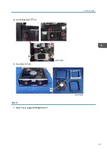
4.

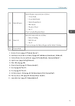
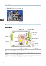
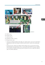
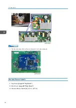
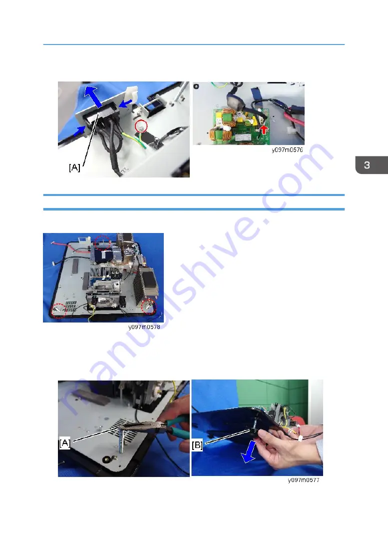
The harness is connected to the PSU.

Adjustable Feet

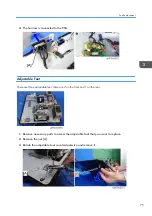
There are three adjustable feet; there are 2 on the front and 1 on the rear.

1.

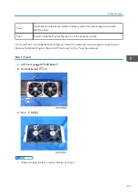
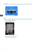
Remove necessary parts to access the adjustable foot that you want to replace.

2.

Remove the nut [A].

3.

Rotate the adjustable foot counterclockwise and remove it.

Part Replacement

75

Содержание LU6000

Страница 1: ...Sargas PJ1 RICOH PJ WUL6280 WXL6280 LU6000 LW6000 Machine Codes Y095 Y096 Y097 Y098 Field Service Manual September 2015 ...

Страница 2: ......

Страница 3: ...age power source can generate ozone gas High ozone density is harmful to human health Therefore the machine must be installed in a well ventilated room Observance of electrical safety standards This machine and its peripherals must be serviced by a customer service representative who has completed the training course on those models Health safety conditions This machine which uses a high voltage p...

Страница 4: ... label shows all information related to laser power CLASS 3R LASER PRODUCT AVOID DIRECT EYE EXPOSURE The laser aperture is from the projection lens DO NOT LOOK INTO THE LENS This projector has a built in Class 4 laser module Unplug the power cord from the outlet with exterior covers open before maintenance operations However if you need to turn the main power on with the covers open to do adjustme...

Страница 5: ...hen turning on the projector make sure no one within projection range is looking at the lens Not following the control adjustment or operation procedure may cause damage by exposure to laser radiation Adequate instructions for assembly operation and maintenance including clear warnings concerning precautions to avoid possible exposure to laser and collateral radiation in excess of the accessible e...

Страница 6: ...Information Overview 9 Main Unit 9 Control Panel 11 Connection Ports 12 Remote Control 13 Specifications 15 Product Highlights 15 General Specifications 15 Compatible Modes 18 Input Signal 18 PIP PBP Compatibility 22 Laser Diode Information 22 Lenses 22 Block Diagram 26 2 Installation Installation Requirements 29 Environment Power Requirements 29 Machine Space Requirements 29 Machine Dimensions 29...

Страница 7: ... Keypad Buttons Top IR Sensor LED Indicator Board 46 LAN Board Main Board IO Board 48 Connection List 52 Vertical Motor Horizontal Motor 54 Light Sensor 56 Filter Wheel 58 Optical Engine Base Unit 60 Fans 62 Fan 1 Fan 2 63 Fan 3 64 Fan 4 65 Fan 5 67 LD Driver Board PSU Thermal Pad 68 Notes for Installation 70 Safety Interlock Switch 72 Thermal Switch 73 Harness Power Switch 74 Adjustable Feet 75 4...

Страница 8: ...ght Sensor ABP Calibration 90 ADC Calibration 91 VGA RGB Calibration 91 VGA YUV Calibration 93 Component YUV Calibration 95 G Sensor Calibration 97 Re write Serial Number 99 Equipment Needed 99 Re write Serial Number 99 Connection and projector setting 99 Re write serial number 100 Check Serial Number SN 101 Factory Reset 103 Factory Reset Procedure 1 103 Factory Reset Procedure 2 103 5 Troublesho...

Страница 9: ...Machine with a Web Browser 121 Connecting the Projector Checking the LAN Setting 121 PC Network Setting 122 Proxy Setting 123 7 Firmware Update PW392 PIC FW Update 127 Equipment Needed 127 Firmware Update Procedure 127 Check the PW392 and PIC FW Version 132 LAN Firmware Update 133 Equipment Needed 133 LAN FW Update Procedure 133 Check the LAN FW Version 137 8 Detailed Description Laser 139 Labelli...

Страница 10: ...Projection Light 145 Light 145 8 ...

Страница 11: ...1 Product Information Overview Main Unit Front view Rear view 1 Front IR receiver 2 Projection lens 3 Lens ring 4 Adjustable feet 5 LED status indicators 6 Top IR sensor 9 ...

Страница 12: ...7 Connector panel 8 Power switch 9 Power connector 10 Kensington lock 11 Security bar 12 Inlet vent 13 Control panel Right view Left view 1 Inlet vent 2 Outlet vent 1 Product Information 10 ...

Страница 13: ...r exits the menu if at the top level 5 Arrow keys Adjusts a setting UP or DOWN Navigates within a menu 6 AV mute key Displays or blanks the video image 7 Input key Selects an input for the main or PIP PBP image 8 Zoom key Adjusts zoom 9 Focus key Adjusts focus 10 Auto key Automatically optimizes the image 11 Lens key Adjusts the lens vertical or horizontal offset setting Overview 11 ...

Страница 14: ...nectors 3 HDMI connector 4 VGA IN connector 5 VGA OUT connector 6 DVI D connector 7 Ethernet connector 8 USB Type A connector 9 Mini USB connector for LAN firmware update only 10 RS232 connector PC control 11 Component IN connectors 1 Product Information 12 ...

Страница 15: ...Remote Control Ind Part Name Description 1 Power on Turns the projector ON 2 Number key Enters a number such as a value for an IP address etc Overview 13 ...

Страница 16: ...cally 12 Keystone H Adjusts the horizontal keystone 13 Keystone V Adjusts the vertical keystone 14 Shutter AV Mute Displays or blanks the video image 15 Hot Key Selects your preset keys quickly 16 OFF Turns the projector OFF 17 Mode Selects the preset display mode 18 Source Selects an input for the main or PIP PBP image 19 Exit Returns to the previous level or exits the menus if at the top level 2...

Страница 17: ...tation operation General Specifications No Item Description 1 Technology TI 0 65 XGA DMD Type A DC3 TI 0 67 WUXGA DMD Type A DC3 2 Dimension W x D x H 484 x 525 x 186 mm without lens w o elevators 3 Weight Net weight w o lens 18 kg Gross Weight with Type A3 lens 18 5 kg Weight with package w o lens 22 5 kg 4 Power supply Auto ranging 100V 240V 10 50 60Hz 400W Laser Diode Normal operation 240W Lase...

Страница 18: ... WXGA 1 00 1 28 Replacement Lens Type A2 1 28 1 61 Standard Lens Type A3 1 60 3 07 Replacement Lens Type A4 3 04 5 78 Replacement Lens Type A5 0 79 1 00 Replacement Lens Type A1 10 LD life Normal mode 20 000 hours standard 3 5W 50 survival rate 11 Video compatibility NTSC NTSC M 3 58MHz 4 43MHz PAL PAL B D G H I M N 4 43MHz SDTV 480i p 576i p HDTV 720p 50 60Hz 1080i p 50 60Hz 1080p 24 25 30 50 60 ...

Страница 19: ...GA 80 WUXGA White ANSI Standard Lens Center Standard 15 WXGA 15 WUXGA Minimum 30 WXGA 30 WUXGA Black ANSI Standard Lens Center Standard 30 WXGA 30 WUXGA Minimum 50 WXGA 50 WUXGA 15 Filter wheel 4 Segment RYGB Filter Diameter 65mm R98 G90 Y118 B54 Speed 7200 Hz 16 Color Coordinate Chromaticity 0 025 White X 0 3181 Y 0 3405 Red X 0 6347 Y 0 3598 Green X 0 2973 Y 0 6271 Blue X 0 1601 Y 0 0166 17 Proj...

Страница 20: ... be different 2 Uniformity is measured in bright display mode normal brightness mode and lens shift on center 3 The temperature displayed in System Temperature in Information in OPTION in the OSD menu indicates the temperature inside the enclosure so it is not a problem even if it exceeds 40 C 104 F Compatible Modes Input Signal Signal Resolution Refresh rate Hz VGA Compon ent HDMI DVI HDBaseT PC ...

Страница 21: ...C 1024 x 768 60 O O O O PC 1024 x 768 75 O O O O PC 1024 x 768 85 O O O O PC 1152 x 720 50 O O O PC 1152 x 720 60 O O O PC 1152 x 720 75 O O O PC 1152 x 720 85 O O O PC 1152 x 864 60 O O O O PC 1152 x 864 70 O O O O PC 1152 x 864 75 O O O O PC 1152 x 864 85 O O O O PC 1152 x 870 75 O O O PC 1280 x 720 50 O O O PC 1280 x 720 60 O O O O PC 1280 x 720 75 O O O O PC 1280 x 720 85 O O O O PC 1280 x 768...

Страница 22: ...PC 1280 x 960 60 O O O O PC 1280 x 960 75 O O O O PC 1280 x 960 85 O O O O PC 1280 x 1024 50 O O O PC 1280 x 1024 60 O O O O PC 1280 x 1024 75 O O O O PC 1280 x 1024 85 O O O O PC 1360 x 768 50 O O O PC 1360 x 768 60 O O O PC 1360 x 768 75 O O O PC 1360 x 768 85 O O O PC 1366 x 768 60 O O O O PC 1400 x 1050 50 O O O PC 1400 x 1050 60 O O O PC 1400 x 1050 75 O O O O PC 1440 x 900 60 O O O O PC 1440...

Страница 23: ... x 1200RB 50 O O O O PC 1920 x 1200RB 60 O O O O SDTV 480i 60 O O O O O 576i 50 O O O O O EDTV 480p 60 O O O O O 576p 50 O O O O O HDTV 1080i 25 O O O O O 1080i 29 O O O O O 1080i 30 O O O O O 720p 50 O O O O O 720p 59 O O O O O 720p 60 O O O O O 1080p 23 O O O O O 1080p 24 O O O O O 1080p 25 O O O O O 1080p 29 O O O O O 1080p 30 O O O O O 1080p 50 O O O O O 1080p 59 O O O O O Specifications 21 ...

Страница 24: ...lanking PIP PBP Compatibility Input Signal HDMI VGA Component HDBaseT DVI D HDMI O VGA O Component O HDBaseT O DVI D O O O O Laser Diode Information Description Type 3 5W LD life Normal mode 20 000 hours standard 3 5W 50 survival rate The above spec is only claimed for table top and ceiling mount LD power Normal mode 3 5W 2 3A Lenses WXGA WUXGA Type A3 is the standard lens 1 Product Information 22...

Страница 25: ...Focus spec MTF 67 lp mm 47 lp mm 67 lp mm 67 lp mm 67 lp mm Zoom range ratio 1 28X 1 25X 1 9X 1 9X 1 26X Zoom focus adjustment Motorized Throw ratio WXGA 1 00 1 28 1 28 1 61 1 60 3 07 3 04 5 78 0 79 1 00 Throw distance WXGA 1 08 8 27m 1 38 10 40m 1 72 19 84m 3 27 37 35m 0 83 6 45m Throw ratio WUXGA 0 95 1 22 1 22 1 53 1 52 2 92 2 90 5 50 0 75 0 95 Throw distance WUXGA 1 02 7 88m 1 31 9 89m 1 64 18...

Страница 26: ... tolerance 4 1 2 screen image Replacement Lens Type A2 A3 A4 A5 0 65 WXGA H 30 V 100 0 67 WUXGA H 30 V 100 Replacement Lens Type A1 0 65 WXGA H 15 V 50 0 67 WUXGA H 15 V 50 Lens shift accuracy 0 5 pixel per step When the lens is shifted beyond the recommended range for operation the screen edges may become darker or the images may become out of focus Keystone correction V 20 degrees Leakage 0 8 Lx...

Страница 27: ... Type A1 Distortion 1 0 100 screen size all lens shift areas all optional lenses Horizontal distortion A C C up and B C C down Vertical distortion D E 2F 2F Flare Flare 2 5 pixels Excl core pixel 100 screen Unbalance 50cm 100 full range for all lenses Image Quality Follows TI DMD Image Quality Specification IQ 8 Specifications 25 ...

Страница 28: ...Block Diagram 1 Product Information 26 ...

Страница 29: ...Block Diagram 27 ...

Страница 30: ...1 Product Information 28 ...

Страница 31: ... inside the enclosure so it is not a problem even if it exceeds 40 C 104 F Power supply 100 to 240VAC 10 50 to 60Hz Auto ranging and power factor correction Machine Space Requirements Do not block projector in out air vents Keep 30 cm clearance around vents for air flow Leave a space of 100 cm or more between the projectors if they are installed side by side Machine Dimensions 484 mm W x 525 mm D ...

Страница 32: ...of this machine follow the contents with reference to Safety Information in the user manual Accessory Check No Description Q ty 1 Projector Lens is not included 1 2 Lens cover 1 3 Power cord 1 4 VGA cable 1 5 Remote control 1 6 AA R6 batteries for remote control 2 2 Installation 30 ...

Страница 33: ...p when the projector is in operation Do not look into or point the laser pointer on your remote control into your or someone s eyes Laser pointers can cause permanent damage to eyesight Do not transport the projector with any lens installed Do Turn OFF and unplug the power plug from the AC outlet before cleaning the product Use a soft dry cloth with mild detergent to clean the display housing Disc...

Страница 34: ... In areas susceptible to excessive dust and dirt Near any appliance generating a strong magnetic field In direct sunlight 2 Installation 32 ...

Страница 35: ...mware and to perform adjustments that are necessary after replacing the optical engine page 60 Optical Engine Base Unit or main board page 48 LAN Board Main Board IO Board 1 RS 232C cable cross 9pin 9pin 2 USB cable Type A to Mini B 3 Laptop with terminal emulator software which is required for collecting error logs and updating firmware 33 ...

Страница 36: ...Equipment Needed 1 Screw bit 105 2 Screw bit 107 3 Screw bit 107 4 Hex sleeves 5 mm 5 Needle nose pliers 6 Projector 3 Replacement 34 ...

Страница 37: ...e 8 Fan 4 9 Fan 5 10 Top cover 11 Rear cover 12 Front cover 13 Left cover 14 Right cover 15 Keypad board 16 Keypad button 17 Interlock switch 18 Main board 19 I O board 20 LAN board 21 PSU 22 Harness Power SW AC inlet 23 Filter wheel and sponge rubber 24 Thermal switch 25 Motor 26 LED indicator board PCB 27 Cable tie 28 Light sensor Parts List 35 ...

Страница 38: ...he laser safety level is class II Appropriate laser safety eyewear must be worn if practicable while removing the top cover to do adjustment procedures Lens Ring Projector Lens 1 Pull out the lens ring A 3 Replacement 36 ...

Страница 39: ... rotate it carefully Then remove the projector lens carefully Be careful not to dirty the glass of the projector lens Be careful not to touch the motor A B of the projector lens Exterior Covers Location of screws Part Replacement 37 ...

Страница 40: ...ng covers For example Screw 1 fastens the left and rear covers If a cover is difficult to remove removing the screws of its adjoining cover will make it easier to remove the cover Top Cover 1 Remove 4 screws on the back cover x4 3 Replacement 38 ...

Страница 41: ...crews on the left cover x4 4 Pull to remove the top cover A The flat screw A and round screw B are used on the top cover Be careful not to insert the wrong screws Doing so will make it impossible to remove the screws and the top cover Part Replacement 39 ...

Страница 42: ...Rear Cover 1 Top Cover page 38 Top Cover 2 Remove 4 screws on the upper side x4 3 Remove 6 screws red circles and 8 hex screws yellow circles on the back side x14 3 Replacement 40 ...

Страница 43: ...4 Rear Cover A x1 Front Cover Front IR Sensor 1 Top Cover page 38 Top Cover 2 Top Shielding A x11 3 Disconnect the front IR sensor connector x1 IR is printed on the main board Part Replacement 41 ...

Страница 44: ...4 Front Cover A x6 5 Front IR Sensor A 2 hooks 3 Replacement 42 ...

Страница 45: ...Left Cover 1 Top Cover page 38 Top Cover 2 Top Shielding A x11 3 Disconnect the fan1 2 connectors x2 R Fan1 and R Fan2 are printed on the main board Part Replacement 43 ...

Страница 46: ...4 Left Cover A x6 Right Cover 1 Top Cover page 38 Top Cover 3 Replacement 44 ...

Страница 47: ...1 Top Shielding A x11 2 Disconnect the fan 5 connector x1 F Fan5 is printed on the main board 3 Remove the screws for the right cover x6 Part Replacement 45 ...

Страница 48: ...4 Remove the safety interlock switch A x2 5 Right Cover A Keypad Board Keypad Buttons Top IR Sensor LED Indicator Board A Keypad Board and Keypad Buttons 3 Replacement 46 ...

Страница 49: ... indicator Board C Top IR Sensor 1 Rear Cover page 40 Rear Cover 2 Keypad Board A and Keypad Buttons B x6 x2 3 LED Indicator Board x2 x2 4 Top IR sensor with bracket A x2 x1 black seal x2 Part Replacement 47 ...

Страница 50: ...5 Separate the Top IR sensor A and the bracket LAN Board Main Board IO Board 1 Top Cover page 38 Top Cover 2 Top Shielding A x11 3 Replacement 48 ...

Страница 51: ...3 LAN Board A x3 x2 There are 2 connectors A at the back side Part Replacement 49 ...

Страница 52: ...and PSU must be connected to the matching board After disconnecting the harness if you connect the LVPS end to the PSU the power will fail to turn on Mark the connectors and boards as shown in the red frame so as to indicate the matching pairs of connectors and boards 3 Replacement 50 ...

Страница 53: ...tor A at the back side of the main board Pull the main board upward and then remove it 5 Turn the main board upside down and then remove the IO board A x3 x2 There are 2 connectors A at the back side Part Replacement 51 ...

Страница 54: ...Red Black Yellow wire green connector 3 pins B R Fan 3 Red Blue Black wire White connector and Black tube 3 pins C R Fan 4 Composed of Red Blue Black wire White connector and Black tube 3 pins D F Fan 5 Composed of Red Blue Black wire White connector 3 pins 3 Replacement 52 ...

Страница 55: ...or and Black tube 3 pins I F W Sensor Composed of White Red Black wire Red connector and Black tube 3 pins J FW Motor Blue connector and flat cable K H Sensor L Composed of White White wire White connector and Black tube 2 pins L V Sensor B Composed of Black Black wire White connector and Black tube 2 pins M Driver DB 20 pins N V Sensor T Composed of Blue Blue wire White connector and Black tube 2...

Страница 56: ...r and Black tube 4 pins S Keypad Black tube 30 pins T Light Sensor Composed of Red Yellow Black wire White connector and Black tube 3 pins U LVPS 22 pins V R Fan 2 Composed of Red Blue Black wire White connector and Black wire tube 3 pins W R Fan 1 Composed of Red Blue Black wire White connector and Black tube 3 pins Vertical Motor Horizontal Motor 1 Top Cover page 38 Top Cover 2 Front Cover page ...

Страница 57: ...3 Top shielding A x11 4 Disconnect the horizontal motor connector A and vertical motor connector B x2 Motor V and Motor H are printed on the main board 5 Front Shielding A Part Replacement 55 ...

Страница 58: ...6 Horizontal Motor A and Vertical Motor B The horizontal motor and vertical motor are the same part interchangeable Light Sensor 1 Top Cover page 38 Top Cover 3 Replacement 56 ...

Страница 59: ... Shielding A x11 3 Disconnect the light sensor connector x1 Light Sensor is printed on the main board 4 Sensor Cover A x1 Peel the sponge seal if the screw is covered with the sponge seal Part Replacement 57 ...

Страница 60: ...5 Light Sensor A Filter Wheel 1 Top Cover page 38 Top Cover 2 Main Board page 48 LAN Board Main Board IO Board 3 Bottom Shielding A x6 3 Replacement 58 ...

Страница 61: ... sponge seal A x2 The sponge seal B is attached to prevent the entry of dust 6 Filter Wheel A x2 Do not touch the wheel part B Be careful not to bump the wheel against anything when you replace it because it breaks easily Part Replacement 59 ...

Страница 62: ...Optical Engine Base Unit Optical Engine A Base Unit B and 2 Thermal Pads C are integrated and provided as a one piece unit 3 Replacement 60 ...

Страница 63: ...ng C Thermal Pads 1 Exterior Covers page 37 Exterior Covers 2 LAN Board Main Board IO Board page 48 LAN Board Main Board IO Board 3 Vertical Motor Horizontal Motor page 54 Vertical Motor Horizontal Motor 4 Light Sensor page 56 Light Sensor 5 Filter Wheel page 58 6 Thermal Switch page 73 Thermal Switch 7 Fan 3 page 64 Fan 3 8 Fan 4 page 65 Fan 4 9 LD Driver Board PSU page 68 LD Driver Board PSU The...

Страница 64: ...s of the fans Fan 1 2 Exhaust fan mounted on the left cover Fan 3 Intake fan mounted on the optical engine to cool the phosphor wheel Fan 4 Intake fan to cool the laser bank Fan 5 Intake fan mounted on the right cover to cool the laser bank 3 Replacement 62 ...

Страница 65: ...ool the phosphor wheel Fan 6 and Fan 7 are inside the Optical Engine Base Unit where the service engineer cannot access Replace the Optical Engine Base Unit if Fan 6 and or Fan 7 must be replaced Fan 1 Fan 2 1 Left Cover page 43 Left Cover 2 Fan Bracket A x4 3 Fan 1 2 A B When attaching the fans wire the harness as shown Part Replacement 63 ...

Страница 66: ...Fan 3 1 Top Cover page 38 Top Cover 2 Top Shielding A x11 3 Disconnect the fan 3 connector x1 R Fan 3 is printed on the main board 3 Replacement 64 ...

Страница 67: ...4 Fan Bracket A x2 5 Fan 3 A Fan 4 Fan 4 A is located next to the heat sink B Part Replacement 65 ...

Страница 68: ...1 Top Cover page 38 Top Cover 2 Top Shielding A x11 3 Disconnect the fan 4 connector x1 R FAN4 on Main Board 3 Replacement 66 ...

Страница 69: ...4 Fan Bracket A x3 5 Fan 4 A x2 Fan 5 1 Right Cover page 44 Right Cover Part Replacement 67 ...

Страница 70: ...2 Fan Bracket A x4 3 Fan 5 A x6 LD Driver Board PSU Thermal Pad 1 Bottom Shielding A x6 3 Replacement 68 ...

Страница 71: ...2 Bracket A x6 3 Horizontal Motor with bracket A x2 4 LD Driver Board Casing A x3 x4 Part Replacement 69 ...

Страница 72: ...5 LD Driver Board A x4 6 Thermal Pad A 2 pads 7 PSU A x6 x5 Notes for Installation Connect the PSU connector properly so as to prevent connection failure or misconnection 3 Replacement 70 ...

Страница 73: ...tep be careful not to forget to connect the interlock switch connector when replacing the PSU Each end connector of the harness linking the LVPS and PSU must be connected to the matching board After disconnecting the harness if you connect its LVPS end to the PSU the power will fail to turn on Mark the connectors and boards as shown in the red frame so as to indicate the matching pairs of connecto...

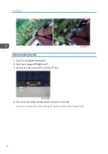
Страница 74: ...38 Top Cover 2 Right Cover page 44 Right Cover 3 Remove the Safety Interlock Switch A x2 4 Disconnect the Safety Interlock Switch connector on the PSU For how to access the PSU refer to page 68 LD Driver Board PSU Thermal Pad 3 Replacement 72 ...

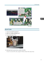
Страница 75: ...ver page 38 Top Cover 2 Right Cover page 44 Right Cover 3 Thermal Switch A x1 4 Disconnect the Thermal Switch connector on the PSU For how to access the PSU refer to page 68 LD Driver Board PSU Thermal Pad Part Replacement 73 ...

Страница 76: ... The thermal sensor A on the main board is not to be replaced Harness Power Switch 1 Top Cover page 38 Top Cover 2 Rear Cover page 40 Rear Cover 3 Harness Power Switch A x1 x1 3 Replacement 74 ...

Страница 77: ... There are three adjustable feet there are 2 on the front and 1 on the rear 1 Remove necessary parts to access the adjustable foot that you want to replace 2 Remove the nut A 3 Rotate the adjustable foot counterclockwise and remove it Part Replacement 75 ...

Страница 78: ...3 Replacement 76 ...

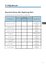
Страница 79: ...in board Optical Engine base unit Filter wheel System firmware update page 127 PW392 PIC FW Update Filter wheel index page 81 Adjustment Phosphor wheel index page 81 Adjustment Factory reset page 103 Factory Reset Lens calibration page 90 Calibration Light Sensor ABP calibration page 90 Calibration ADC calibration page 90 Calibration G sensor calibration page 90 Calibration 77 ...

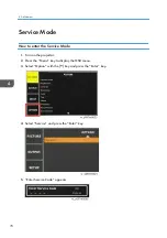
Страница 80: ...r the Service Mode 1 Turn on the projector 2 Press the Menu key to display the OSD menu 3 Select Option with the key and press the Enter key 4 Select Service and press the Enter key 5 Enter Service Code appears 4 Adjustment 78 ...

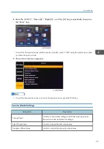
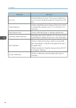
Страница 81: ...The service mode menu appears To exit from the service mode or return to the previous menu press the Exit key Service Mode Settings Setting Item Description Factory Reset Use this to reset all the settings in the OSD menu except for the service mode and network settings Filter Wheel Index Use this to adjust the filter wheel index Phosphor Wheel Index Use this to adjust the phosphor wheel index Ser...

Страница 82: ...t the machine s cumulative operation time Light Sensor ABP Calibration During light sensor ABP calibration the color balance of the projected light is adjusted using a sensor in the optical engine ADC Calibration Use this to calibrate the analog to digital converter ADC Black level adjustment Adjust the analog black level 0 V to the digital 0 level White level adjustment Adjust the analog white le...

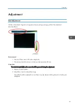
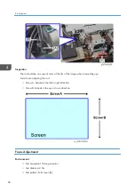
Страница 83: ... screen is 60 inches diagonally This process should be done in a dark environment under 20 lux Procedure The interlock switch C on the cover should be pressed during the adjustment 1 Display a white pattern 2 Adjust the screws to readjust the image Screw B should be adjusted first and then screw A Adjust until the yellowish or bluish parts disappear Adjustment 81 ...

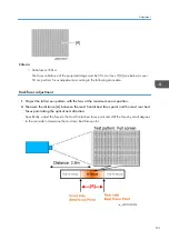
Страница 84: ...mage when viewed by eye Avoid over adjusting the rod Screw A Adjusts in the left or right direction Screw B Adjusts in the up or down direction Focus Adjustment Environment Test equipment Video generator Test distance 2 5m Test pattern Full screen A 4 Adjustment 82 ...

Страница 85: ...stment 1 Project the full screen pattern with the lens at the maximum zoom position 2 Measure the distance A between the most frontal best focus point and the most rear best focus point along the optical axis direction Specifically adjust the focus to the most frontal best focus point and shift the focus by small degrees to the rear side to determine the most rear best focus point Adjustment 83 ...

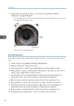
Страница 86: ...ion 1 is in focus check position 2 If position 2 is not in focus use the Up or Down key to adjust the focus until it is in focus 5 If pressing the Up key can focus position 2 adjust setscrew B counterclockwise If pressing the Down key can focus position 2 adjust setscrew B clockwise 6 Refocus position 1 and see if position 2 is also in focus If not repeat steps 3 to 6 7 Ensure position 1 is in foc...

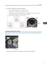
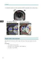
Страница 87: ...e than 8 screws A B and C should be recovered to the default tooth positions see Checking the Default Gear Position below and re adjusted Checking the Default Gear Position Before the projector shipment a mark A will be made on the gear to show the best match position of each gear set 1 Rotate the screws A B and C respectively counterclockwise until it stops Adjustment 85 ...

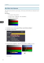
Страница 88: ...s shown below Phosphor Wheel Index Adjustment After replacing the main board or optical engine the Phosphor Wheel Index Adjustment should be done Environment Test equipment Video generator Test signal 1920 x 1200 60Hz 1280 x 800 60Hz Test pattern 64 gray RGBW 4 Adjustment 86 ...

Страница 89: ...d gray gradations until they are even A Not good Inspection item Check if each color level is correct Color saturation Criteria Screen appears satisfactory There should be no unusual conditions such as lines on the screen Color levels should be sufficient and satisfactory Blue level should not have unusual color or heavy lines Adjustment 87 ...

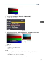
Страница 90: ...should be done Environment Test equipment Video generator Test signal 1920 x 1200 60Hz 1280 x 800 60Hz Test Pattern 256 gray RGBW 1 Get into the Service mode page 78 How to enter the Service Mode 2 Select Filter Wheel Index 3 Using the Left or Right key adjust the gray gradations until they are even A Not good 4 Adjustment 88 ...

Страница 91: ...orrect Color saturation Criteria Screen appears satisfactory There should be no unusual conditions such as lines on the screen Color levels should be sufficient and satisfactory Gray level should not have unusual color or heavy lines Adjustment 89 ...

Страница 92: ...libration 4 Select Yes and then press Enter Light Sensor ABP Calibration After replacing the main board optical engine or filter wheel Light Sensor ABP Calibration must be done During light sensor ABP calibration the color balance of the projected light is adjusted using a sensor in the optical engine The laser light source separately creates RGB and other light beams This function is used to adju...

Страница 93: ...r replacing the main boar this calibration must be done VGA and Component signals require ADC calibration VGA RGB Calibration Environment Test equipment Video generator Test signal 800 x 600 72Hz Test pattern Grays 16 Input the signal from the VGA IN port 1 Connect the video source and wait for the screen display 2 Get into service mode page 78 How to enter the Service Mode Calibration 91 ...

Страница 94: ...n press the Enter key 4 SOP will show up on screen 5 Press the Auto key and the process will start The screen will flash during calibration processing 6 After the process is done press the Enter key to refresh the SOP 4 Adjustment 92 ...

Страница 95: ...e default values the calibration has failed When the calibration failed check the video source and redo the ADC calibration VGA YUV Calibration Environment Test equipment Video generator Test signal 720p 60Hz Test pattern SMTE pattern Input the signal from the VGA IN port 1 Get into the service mode page 78 How to enter the Service Mode Calibration 93 ...

Страница 96: ...ss the Enter key 3 SOP will show up on screen 4 Press the Auto key and the process will start The screen will change color during calibration processing 5 After the process is done press the Enter key to refresh the SOP 4 Adjustment 94 ...

Страница 97: ...default values the calibration has failed When the calibration failed check the video source and redo the ADC calibration Component YUV Calibration Environment Test equipment Video generator Test signal 720p 60Hz Test pattern SMPTE BAR Input the signal from the Component IN port 1 Get into service mode page 78 How to enter the Service Mode Calibration 95 ...

Страница 98: ...ss the Enter key 3 SOP will show up on screen 4 Press the Auto key and the process will start The screen will change color during calibration processing 5 After the process is done press the Enter key to refresh the SOP 4 Adjustment 96 ...

Страница 99: ...s the calibration has failed When the calibration failed check the video source and redo the ADC calibration G Sensor Calibration After replacing the main board this calibration must be done 1 Put the projector on a horizontal surface 2 Get into service mode page 78 How to enter the Service Mode 3 Select G Sensor Calibration and then press the Enter key Calibration 97 ...

Страница 100: ...When the calibration has finished a message appears 4 Adjustment 98 ...

Страница 101: ...Re write Serial Number tool Hardware 1 Projector 2 Power cord 3 Female to female RS232 cable cross 9pin 9pin 4 Laptop Re write Serial Number Connection and projector setting 1 Connect the projector and PC with the RS232 cable Re write Serial Number 99 ...

Страница 102: ...he Menu key to enter the OSD menu 4 Select SETUP Communications Serial Port Baud Rate 115200 Re write serial number 1 Double click the Re write Serial Number tool file XXXX Tester for re write SN exe 2 Execute HPBU_Common Tester Ensure that the projector baud rate is 115200 4 Adjustment 100 ...

Страница 103: ...ter the serial number for example 9492341007 and then Click RUN to re write the Serial Number The Pass and Normal Mode messages will be shown in the window Check Serial Number SN 1 Press the Menu key to enter the OSD menu Re write Serial Number 101 ...

Страница 104: ...2 Select OPTION Information 3 Check the serial number 4 Adjustment 102 ...

Страница 105: ...do Factory Reset Either way the settings to be reset are the same After replacing the main board Factory Reset must be done Factory Reset Procedure 1 1 Press the Menu key to enter the OSD menu 2 Select Option Factory Reset 3 Select Yes and then press the Enter key Factory Reset Procedure 2 1 Get into service mode page 78 How to enter the Service Mode Factory Reset 103 ...

Страница 106: ...2 Select Factory Reset 3 Select Yes and then press the Enter key 4 Adjustment 104 ...

Страница 107: ... and the projection screen Check the projection lens to see if it needs cleaning Moving the projector from a cool to a warm place may result in condensation on the projection lens In this case leave the projector off and wait until the condensation evaporates No image Check the connection between your computer or video equipment and the projector See if the input signal is correctly output from yo...

Страница 108: ...tart up A PIN code lock is set Input a PIN code 1234 or numbers you have set Remote Control does not work Check the batteries Make sure there is no obstruction between the projector and the remote controller Make sure you are not too far from the projector when using the remote controller Maximum operating range is 32 8 5m Make sure the ID code of the remote controller conforms with the projector ...

Страница 109: ...lug in Off AC has been applied and the projector is in standby mode NOTE The Status LED is off but the LED on the power key will indicate Standby Mode 1 Solid Green The projector is powered up and operating normally Flashing Green The projector is communicating Flashing Orange The projector is in cool down mode or startup mode Flashing alternating Green Orange The projector is in the flash update ...

Страница 110: ...LED Type LED Status Projector State AV MUTE Solid Green Light is on an image is displayed Solid Orange Light is on the image is blank 1 Standby mode 5 Troubleshooting 108 ...

Страница 111: ...escription Actions 0 No Error No Error recorded None 1 Lamp Ignite Fail Laser failed to ignite Check laser banks and replace Optical Engine base unit if necessary 5 Format Board Power On Fail Main board failed to power on and projector auto shutdown Replace main board 6 Color Wheel Unexpected Stop Filter wheel unexpected stop and projector auto shutdown Check filter wheel and replace it if necessa...

Страница 112: ...ary 26 LD lower than 60 Filter wheel or Optical Engine is defective Replace Filter wheel or Optical Engine base unit 28 LD NTC 1 Over Temperature Laser bank 1 over temperature and projector auto shutdown Check fans or intake vent Replace fans if necessary 30 LD NTC 2 Over Temperature Laser bank 2 over temperature and projector auto shutdown Check fans or intake vent Replace fans if necessary 31 Hi...

Страница 113: ...er cord 3 Female to female RS232 cable cross 9pin 9pin 4 Laptop Procedure 1 Connect the projector and the PC with the RS232 cable 2 Power on the projector 3 Press the Menu key to enter the OSD menu Error Log Troubleshooting 111 ...

Страница 114: ... terminal emulation software 6 Set the baud rate to 115200 with the terminal emulation software 7 Set the following terminal settings Receive AUTO Transmit CR LF Local echo Enable 8 With the terminal emulation software enter elog to see the error log 5 Troubleshooting 112 ...

Страница 115: ...9 Check the error log information For descriptions of the error codes see Checking the Error Log Service Mode Menu page 109 Checking the Error Log Service Mode Menu Error Log Troubleshooting 113 ...

Страница 116: ...5 Troubleshooting 114 ...

Страница 117: ...ipped with Component and HDMI HDTV source 480P 720P 1080P You can also use a computer with an HDMI port Recommended Test Condition Ambient brightness Dark room less than 2 lux Screen size 60 inches diagonal Zone Definition Zone A The blue area in the center of the image Zone B The outside of the image 115 ...

Страница 118: ...teria A stands for Zone A B stands for Zone B For WXGA Order Symptom Pattern Criteria 1 Bright pixels dots Gray 10 A B 0 2 Dark pixels dots Blue 60 A 0 B 7 3 Bright blemishes Gray 10 A 0 B 4 diameter 1 4 Dark blemishes Blue 60 A 0 B 4 diameter 1 6 Test Inspection 116 ...

Страница 119: ...0 6 Unstable pixels Any pattern A B 0 7 Adjacent dark pixels Any pattern A B 0 For WUXGA Order Symptom Pattern Criteria 1 Bright pixels dots Gray 10 A B 0 2 Dark pixels dots White A 0 B 2 3 Bright blemishes Gray 10 A 0 B 4 diameter 1 Test Equipment and Conditions 117 ...

Страница 120: ...r Symptom Pattern Criteria 4 Dark blemishes Blue 60 A 0 B 4 diameter 1 5 Bright dots in the frame Gray 10 1 6 Unstable pixels Any pattern A B 0 7 Adjacent dark pixels Any pattern A B 0 6 Test Inspection 118 ...

Страница 121: ...s High pitched sound from the cooling fan and filter wheel is unacceptable Check points Check item Check point Text Pattern Missing letters pattern or blurry prints are unacceptable Exterior Dirt scratches water ripples and uneven color are unacceptable Focus and Zoom Focus and Zoom functions work well Logo Missing logo missing prints and blurred prints are unacceptable Screw All screws should be ...

Страница 122: ...g xxx xxx xxx xxx The xxx fields represent the projector s IP address Example ping 192 168 0 100 5 Check the communication result If communication succeeds The message Reply from xxx xxx xxx xxx bytes xxx time xxms TTL xxx appears The xxx fields vary according to the operating environment If communication fails The message Request timed out or Destination Host Unreachable appears If this happens c...

Страница 123: ... Tools Configure the network and password settings D Info Display the projector information E ReSync Re sync the input signal F Mute Display or blank the video image G Freeze Contrast Brightness Color You can adjust each of these settings Connecting the Projector Checking the LAN Setting 1 Plug the LAN cable into the projector 2 Turn ON the projector then press the Menu key to access the OSD menu ...

Страница 124: ...e that DHCP is Off 5 Write down the IP address and subnet mask 192 168 0 100 and 255 255 255 0 in this example PC Network Setting 1 Double click Local area connection then choose Properties 6 Test Inspection 122 ...

Страница 125: ... to 255 255 255 0 The subnet mask of the PC must be the same as the projector The HOST ID or IP address 192 168 0 XXX of the PC must be different from the projector IP address written down earlier 4 Click OK 5 Click Close to quit the setting screen Proxy Setting This section uses Internet Explorer as an example Network Test 123 ...

Страница 126: ...1 Execute Internet Explorer and then choose Tools Internet Options 2 Select Connections and then click LAN Settings 6 Test Inspection 124 ...

Страница 127: ...3 Cancel selection of the proxy server as shown below and then click OK Network Test 125 ...

Страница 128: ...6 Test Inspection 126 ...

Страница 129: ...Needed Software 1 Firmware FW update file 2 Terminal emulation software such as Tera Term which can support serial port connections Hardware 1 Projector 2 Power cord 3 Female to female RS232 cable cross 9pin 9pin 4 PC Firmware Update Procedure PIC is in included in PW392 So update PW392 firmware first then update PIC firmware 127 ...

Страница 130: ... 3 Unzip the firmware update file and then open the folder corresponding to the projector to be updated WUL6280 LU6000 WUXGA WXL6280 LW6000 WXGA If you select the wrong folder and execute firmware update the projector will fail to project images correctly If this happens repeat the procedure from Step 3 7 Firmware Update 128 ...

Страница 131: ...5 Set as follows Connection Serial COM port According to the serial port setting of the PC Baud Rate 115200 6 Click Flash 7 Turn on the projector and the PW392 firmware update runs automatically Wait about 8 minutes PW392 PIC FW Update 129 ...

Страница 132: ...lf 9 Select the language on the projector The PW392 FW update is completed Continue to the PIC FW update 10 Press the Menu key to enter the OSD menu 11 Select SETUP Communications Serial Port Baud Rate 115200 12 Start the terminal emulation software 7 Firmware Update 130 ...

Страница 133: ...Set the following terminal settings Receive AUTO Transmit CR LF Local echo Enable 15 With the terminal emulation software enter sysg kpud1 to trigger the PIC FW updating process The projector powers off by itself and then starts the updating process PW392 PIC FW Update 131 ...

Страница 134: ...The PIC FW update is completed Check the PW392 and PIC FW Version 1 Press the Menu key to enter the OSD menu 2 Select Option Information 3 Check the PW392 and PIC firmware versions A PW392 firmware version B PIC firmware version C LAN firmware version 7 Firmware Update 132 ...

Страница 135: ...ment Needed Software LAN firmware update file Hardware 1 Projector 2 Power cord 3 USB cable Type A to Mini B 4 Laptop LAN FW Update Procedure 1 Unzip the LAN FW update file 2 Turn ON the Power Switch A and let the projector get into standby mode LAN Firmware Update 133 ...

Страница 136: ...g 5 Connect the USB cable between the PC and the projector 6 The USB driver will be installed on the PC 7 Open the LAN firmware update program folder Select x32 if the computer s operating system is 32 bit or x64 if it is 64 bit The folder names may differ from those shown below 7 Firmware Update 134 ...

Страница 137: ...hUpgrader_xXX exe 9 Set as follows Connection USB2 0 Modes Flash Options Reset Target After Download 10 Click Flash to start updating 11 When the process is completed programming completed appears LAN Firmware Update 135 ...

Страница 138: ...dating does not start the USB driver may not have been installed correctly Follow the steps below to re install the USB driver 1 Open the computer s Device Manager screen 2 Right click on Unknown Device then click Update Driver Software 3 Click Browse my computer for driver software 4 Click Browse 7 Firmware Update 136 ...

Страница 139: ...pes of 64 bit driver amd64 and ia64 Normally select amd64 It also includes Intel x64 Select ia64 if the computer s processor is an Itanium 6 Click Next The driver is installed 7 After the driver installation is complete repeat the LAN firmware update procedure from the beginning Check the LAN FW Version 1 Press the Menu key to enter the OSD menu 2 Select Option Information LAN Firmware Update 137 ...

Страница 140: ...3 Check the LAN firmware version A PW392 firmware version B PIC firmware version C LAN firmware version 7 Firmware Update 138 ...

Страница 141: ... long working lifetime of 20 000 hours or longer minimizing the need to replace the light source 2 The projection start up time is shorter than the lamp light source 3 Unlike the existing lamp the laser light source does not contain mercury and is eco friendly Disadvantages and Challenges 1 Laser light source is expensive 2 Compliance with laws and regulations in different countries Class definiti...

Страница 142: ...green from the blue laser light source Light Source Light Collection Method image Characteristic 1 LED Instant on Long lifetime Maintenance free Increased color gamut Compact projector size 2 Laser LED Hybrid Instant on Long lifetime Maintenance free Brightsync and very high color rates LED Etendue will limit brightness 2000 3500L 3 Laser Phosphor Instant on Long lifetime Scalability from low to h...

Страница 143: ...and the blue dichroic mirror B Using the collimator E the laser irradiation position on the phosphor wheel is adjusted for convergence The phosphor wheel D creates green and yellow lights from the blue light The green and yellow lights reflected by the blue dichroic mirror B The blue light passes without modification To use the blue light as is there is the blue wraparound path C The filter wheel ...

Страница 144: ...or G Filter wheel F DMD Phosphor wheel The phosphor wheel A is divided into 3 segments comprised of the blue transparency yellow phosphor and green phosphor Since the phosphor wheel is prone to heat up the device is equipped with a cooling fan B on its top 8 Detailed Description 142 ...

Страница 145: ...comprised of green blue diffuser red and yellow transparent Combiner module Combiner module is comprised of 2 laser banks A 1 phosphor wheel B and 2 heat pipes C for cooling the laser diodes Laser bank Each laser bank is comprised of 19 laser diodes 5 5 5 and 4 and is cooled by the heat pipe Laser 143 ...

Страница 146: ...Cooling System Location of fans 8 Detailed Description 144 ...

Страница 147: ...in its optical path and then its coherence is lowered as it passes through the filter wheel and other parts so the projection light is not dangerous What s coherence Coherence refers to the characteristic of waves indicating the degree of interference clarity of the interference fringes Natural light and lamp light have diverse light wavelength and direction of radiation Thus they have low coheren...

Страница 148: ... Blue laser light is used for the Blu ray Disc laser light source and optical receivers 8 Detailed Description 146 ...

Страница 149: ...MEMO 147 ...

Страница 150: ...MEMO 148 EN ...

Отзывы: