background image

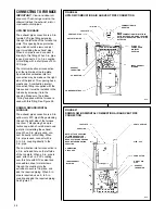
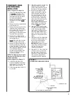
FIGURE 29
DOWNFLOW CONDENSATE DRAIN

CONDENSATE DRAIN/NEUTRALIZER

27

FIGURE 28
UPFLOW CONDENSATE DRAIN

GENERAL INFORMATION

DO NOT RUN DRAIN OUTDOORS.
FREEZING OF CONDENSATE CAN
CAUSE PROPERTY DAMAGE.

IMPORTANT: Do not connect into a
common drain line with an air con-
ditioner evaporator coil drain located
below the furnace. A blocked or
restricted drain line can result in over-
flow of the coil pan and negate the
furnace blocked drain shutoff control.

FILL TRAP ASSEMBLY WITH
WATER BEFORE OPERATING THE
FURNACE.

This can be done by

removing the drain hose
from the trap and pouring about a
cup of water into the vent trap. Water
will flow into the house drain when the
trap is full.

If local codes require, install a
condensate neutralizer cartridge in
the drain line. Install cartridge in
horizontal position only. Also install
an overflow line if routing to a floor
drain. See Figures 28 and 29. 

If no floor drain is available, install a
condensate pump that is resistant to
acidic water. Pumps are available
from your local distributor. If pump
used is not resistant to acidic water, a
condensate neutralizer must be used
ahead of the pump. The condensate
pump must have an auxiliary safety
switch to prevent operation of the
furnace and resulting overflow of
condensate in the event of pump
failure. The safety switch must be
wired through the “R” circuit only (low
voltage) to provide operation in either
heating or cooling modes.

UPFLOW MODELS

The condensate drain trap is located
in the blower compartment on the left-
hand side of the jacket. A short piece
of 

1

/

2

-in. PVC pipe and a 

1

/

2

-in. tee are

provided. Connect the 

1

/

2

-in. pipe to

the elbow on the trap and the tee to
this pipe so that the open end is
upward. Connect at least a 5

(

riser to

the top of the tee and run a drain tube
from the bottom of the tee to a floor
drain or condensate pump. 

IMPORTANT: 

If installing the unit

over a finished ceiling or living area,
be certain to install an auxiliary
condensate drain pan under the
entire unit extending out under the
condensate tee. With a 5 inch riser
installed above the tee, a blocked
drain will result in overflow from the
riser.

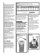
To cause the furnace to shut down
when a blocked drain is present,
install a riser which is a minimum of
10

13

16

(

. If the furnace is installed in an

attic, crawlspace or other area where

freezing temperatures may occur, the
furnace drain can freeze while shut
off for long periods of time. 

Use a solvent cement that is
compatible with PVC material. Cut the
drain hoses to the appropriate length
and connect to the trap with hose
clamps. Tighten the clamps with
pliers and check for leaks after
attaching.

DOWNFLOW MODELS

The condensate trap is located on the
right side of the cabinet in the burner
compartment. A short piece of 

1

/

2

-in.

PVC pipe and a 

1

/

2

-in. tee are

provided. Connect the 

1

/

2

-in. pipe to

the elbow on the trap and the tee to
this pipe so that the open end is
upward. Connect a 5

1

2

-in. riser to the

top of the tee and run a drain tube
from the bottom of the tee to a floor
drain or condensate pump. Use a
solvent cement that is compatible with
PVC material.

!

CAUTION

NEUTRALIZER CARTRIDGE

(OPTIONAL)

TO FLOOR DRAIN OR CONDENSATE PUMP

NOTE:
DRAIN VENT NEEDS
TO BE ABOVE
COLLECTOR BOX
DRAIN SPOUT.

MINIMUM HEIGHT
OPEN TOP

CONDENSATE TRAP

DRAIN LINE

I408

OVERFLOW LINE
(REQUIRED ONLY WHEN
OPTIONAL NEUTRALIZER
CARTRIDGE IS USED.)

I408

MINIMUM HEIGHT
OPEN TOP

DRAIN LINE

CONDENSATE TRAP

TO FLOOR DRAIN OR CONDENSATE PUMP

NEUTRALIZER CARTRIDGE

(OPTIONAL)

OVERFLOW LINE
(REQUIRED ONLY WHEN
OPTIONAL NEUTRALIZER
CARTRIDGE IS USED.)

5

(

Содержание RGRA SERIES

Страница 1: ...er appliance WHAT TO DO IF YOU SMELL GAS Do not try to light any appliance Do not touch any electrical switch do not use any phone in your building Immediately call your gas supplier from a neighbor s...

Страница 2: ...exhaust pipe ft of pipe intake air no of elbows intake air ft of pipe exhaust pipe no of elbows exhaust pipe TERMINATIONS DIRECT VENT VERTICAL Intake 12 min above roof snow level Correct relationship...

Страница 3: ...nsiderations 5 Venting and Combustion Air Piping 12 Combustion and Ventilation Air 14 Vent Pipe Installation 17 Condensate Drain Neutralizer 27 Converting Downflow to Horizontal 29 Gas Supply and Pipi...

Страница 4: ...ble from Canadian Gas Association 55 Scarsdale Road Don Mills Ontario Canada M3B 2R3 24 25 26 27 28 ITEM ITEM NO PART NAME NO PART NAME 1 INDUCED DRAFT BLOWER 15 LOW VOLTAGE TERMINAL 2 CAPACITOR 16 TR...

Страница 5: ...ing evaporator coil with this furnace a be sure the air passes over the heat exchanger before passing over the cooling coil The cooled air passing over the warm ambient air inside the heat exchanger t...

Страница 6: ...rtified by the AGA Laboratories and CGA Laboratories for the clearances to combustible materials shown in inches FIGURE 4 HORIZONTAL FURNACE INSTALLED W SUPPORT BRACKETS GAS PIPE TRAP EXHAUST FAN ELEC...

Страница 7: ...MATERIAL MUST NOT BE PLACED ON OR AGAINST THE FURNACE JACKET THE AREA AROUND THE FURNACE MUST BE KEPT CLEAR AND FREE OF ALL COMBUSTIBLE MATERIALS INCLUDING GASO LINE AND OTHER FLAMMABLE VAPORS AND LI...

Страница 8: ...25 32 0 0 0 1 2 0 111 06 17 1 2 16 11 32 15 5 8 2 15 13 25 32 0 0 0 1 2 0 117 07 17 1 2 16 11 32 15 5 8 2 15 13 25 32 0 0 0 1 2 0 123 09 21 19 27 32 19 1 8 2 18 1 2 17 9 32 0 0 0 1 2 0 148 10 21 19 2...

Страница 9: ...13 7 8 0 0 0 1 2 0 111 06 17 1 2 16 11 32 15 5 8 2 16 5 8 13 7 8 0 0 0 1 2 0 117 07 17 1 2 16 11 32 15 5 8 2 16 5 8 13 7 8 0 0 0 1 2 0 123 09 21 19 27 32 19 3 16 2 20 1 8 17 3 8 0 0 0 1 2 0 148 10 21...

Страница 10: ...17 3 8 0 0 0 1 2 0 148 10 21 19 27 32 19 3 16 2 20 1 8 17 3 8 0 0 0 1 2 0 152 12 24 1 2 23 11 32 22 5 8 2 23 5 8 20 7 8 0 0 0 1 2 0 160 10 I520 A service clearance of at least 24 inches is recommended...

Страница 11: ...ide or back return air do not remove the bottom base b Cut an opening in the side or back The opening should be cut the full width of the knockouts on the unit c Remove the bottom base if using bottom...

Страница 12: ...ORRECT FOR ADEQUATE COMBUSTION AIR SUPPLY DO NOT RESET THE SWITCHES WITHOUT TAKING CORRECTIVE ACTION TO ASSURE THAT AN ADEQUATE SUPPLY OF COMBUSTION AIR IS MAINTAINED UNDER ALL CONDITIONS OF OPERATION...

Страница 13: ...ws exhaust fans fireplace dampers and any other gas burning appliance to their previous conditions of use 7 If improper venting is observed during any of the above tests the common venting system must...

Страница 14: ...ure of the flue products and are highly corrosive after they condense ALL FURNACE INSTALLATIONS MUST COMPLY WITH THE NATIONAL FUEL GAS CODE AND LOCAL CODES TO PROVIDE ADEQUATE COMBUSTION AND VENTILATI...

Страница 15: ...00 11 25 square inches 4 60 000 15 00 square inches 5 75 000 18 75 square inches 5 90 000 22 50 square inches 6 105 000 26 25 square inches 6 120 000 30 00 square inches 6 b Where communicating with o...

Страница 16: ...free area of a 1 square inch for each 3 000 BTUH of the total input rating of all equipment located in the enclosure and BTUH Free Area Round Pipe Input Each Opening Size 45 000 15 00 square inches 4...

Страница 17: ...IRED MINIMUM CLEARANCES TO COMBUSTIBLES ARE MAINTAINED BETWEEN THE PVC PIPE AND OTHER PIPES 5 All vent runs through uncon ditioned spaces where below freezing temperatures are expected should be insul...

Страница 18: ...ents are slightly different in some cases than direct venting Install a non direct vent with the following minimum clearances See Figure 16 1 Locate the bottom of the vent terminal at least 12 inches...

Страница 19: ...llect wrap the vent pipe with self regulating 3 or 5 watt heat tape The heat tape must be WARNING TABLE 2 FOR DIRECT VENT APPLICATIONS AIR FOR COMBUSTION PROVIDED FROM OUTDOORS MAXIMUM ALLOWABLE LENGT...

Страница 20: ...The standard horizontal intake air termination for all models is a 2 in PVC coupling with a wind deflector vane provided attached Cut a 21 4 in length of 2 in PVC pipe Connect this pipe and another 2...

Страница 21: ...termination is made with a closed cell insulation such as Arm a Flex or Rub a Tex with a minimum of 1 2 thickness All elbows installed on the exterior of the building must be of the long sweep nature...

Страница 22: ...pipe 5 21 2 x 21 long PVC pipe 6 PVC vane 7 3 in tee with reducer assembly 8 6 in dia 1 2 in PVC trap 9 PVC strap 10 vent template NOTE The RXGY D04 kit only applies to the 120 000 BTUH unit using an...

Страница 23: ...2 PVC PIPE ON 90 000 THROUGH 120 000 BTUH MODELS REDUCE AND TERMINATE THE LAST 12 INCHES WITH 11 2 PVC PIPE ON 45 000 THROUGH 75 000 BTUH MODELS PITCHED ROOF INSTALLATIONS NOTES SUPPORT HORIZONTAL PIP...

Страница 24: ...m horizontal clearance of 4 feet from electric meters gas meters regulators and relief equipment 6 The air inlet shall be located at least 10 feet horizontally from the vent of any other gas or fuel b...

Страница 25: ...ntenance 9 Do not expose 3 x 2 reducer bushing to outdoor ambient temperatures MULTIVENTING IF VENTING TWO OR MORE FURNACES NEAR EACH OTHER IS REQUIRED EACH FURNACE MUST BE INDIVIDUALLY VENTED NO COMM...

Страница 26: ...p cover This opening has a pro tective cap which should be removed just prior to installing the exhaust pipe When 2 in pipe is used con nect it directly to this fitting When 3 in pipe is used connect...

Страница 27: ...o that the open end is upward Connect at least a 5 riser to the top of the tee and run a drain tube from the bottom of the tee to a floor drain or condensate pump IMPORTANT If installing the unit over...

Страница 28: ...he left Reattach the drain hoses Remove the plastic drainage knockout from the left side See Figure 31 IMPORTANT When changing to the left side interchange the rubber bushing on the right side with th...

Страница 29: ...pped factory ready for downflow installation The condensate trap assembly and drain hoses require conversion for horizontal installation Remove the existing condensate trap with the unit in the uprigh...

Страница 30: ...IGHT POSITION REMOVAL OF EXISTING DOWNFLOW CONDENSATE TRAP FIGURE 34 HORIZONTAL POSITION CONDENSATE TRAP INSTALLATION FOR HORIZONTAL OPERATION I534 CONDENSATE TRAP CONVERSION FROM DOWNFLOW TO HORIZONT...

Страница 31: ...separate gas supply line directly from the meter to the furnace Consult the local gas company for the location of the manual main shut off valve The gas line and manual gas valve must be adequate in s...

Страница 32: ...furnace and its individual shut off valve from the gas supply piping during any pressure testing that exceeds 1 2 p s i g 3 48 kPa GAS PRESSURE Natural gas supply pressure should be 5 to 7 w c LP gas...

Страница 33: ...1 10 mm CANADIAN 0 2000 FT 2001 4500 FT Natural Gas 50 50 LP Gas 1 15 mm 1 15 mm 4 Turn the gas supply back on and check for proper operation and manifold pressure See Figures 39 40 and 41 5 Attach th...

Страница 34: ...units on the same gas line as the furnace 4 Note or adjust the line gas pressure to give A 5 7 w c for natural gas B 11 13 w c for LP gas 5 Shut off the gas at the manual gas valve and remove the U Tu...

Страница 35: ...ELECTRICAL SHOCK PERSONAL INJURY OR DEATH IMPORTANT The furnace must be installed so that the electrical components are protected from water condensate Before proceeding with the electrical connection...

Страница 36: ...44 ISOLATION RELAY TABLE 5 LOW VOLTAGE WIRING SOLID COPPER WIRE AWG 3 0 16 14 12 10 10 10 2 5 16 14 12 12 10 10 2 0 18 16 14 12 12 10 50 100 150 200 250 300 LENGTH OF RUN FEET The total wire length i...

Страница 37: ...7 and Johnson Controls G961DAJ 2401 integrated control boards IMPORTANT TWINNING OF GRJ AND GTJ UNITS REQUIRES AN ACCESSORY TWINNING KIT REFER TO THE SPECIFICATION SHEET FOR PROPER KIT DO NOT ATTEMPT...

Страница 38: ...38 FIGURE 45 HONEYWELL NO S9201E2001 CONTROL BOARD TWINNING CONNECTION SINGLE STAGE OPERATION I400...

Страница 39: ...39 FIGURE 46 HONEYWELL NO S9201E2001 CONTROL BOARD TWINNING CONNECTION TWO STAGE OPERATION I401...

Страница 40: ...40 FIGURE 47 UTEC NO 1012 920 1028 927 CONTROL BOARD TWINNING CONNECTION SINGLE STAGE OPERATION I398...

Страница 41: ...41 FIGURE 48 UTEC NO 1012 920 1028 927 CONTROL BOARD TWINNING CONNECTION TWO STAGE OPERATION I398...

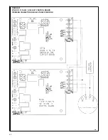
Страница 42: ...42 FIGURE 49 JOHNSON CONTROLS G961DAJ 2401 CONTROL BOARD TWINNING CONNECTION SINGLE STAGE OPERATION I399...

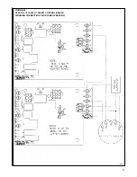
Страница 43: ...43 FIGURE 50 JOHNSON CONTROLS G961DAJ 2401 CONTROL BOARD TWINNING CONNECTION TWO STAGE OPERATION I399...

Страница 44: ...e inducer continues and the igniter stays energized 4 If flame is not sensed during the ninth second after the gas valve opens the gas valve closes and the igniter de energizes 5 After a 30 second int...

Страница 45: ...er firing beyond its design rated input NEVER SET INPUT ABOVE THAT SHOWN ON THE RATING PLATE Use the following table or formula to determine input rate Start the furnace and measure the time required...

Страница 46: ...meter in the supply air duct stops rising approximately five minutes subtract the return air temperature from the supply air temperature The difference is the temperature rise 5 Compare the measured t...

Страница 47: ...1300 1255 HIGH 1705 1665 1615 1570 1540 1475 1400 RGTA 07 12 X 7 1 2 3 4 LOW 1185 1160 1140 1115 1095 1065 1040 M LO 1405 1375 1350 1310 1270 1235 1195 M HI 1595 1560 1525 1480 1440 1380 1325 HIGH 18...

Страница 48: ...LOW 1235 1210 1180 1150 1120 1075 1035 MED 1490 1465 1445 1405 1375 1315 1255 HIGH 1720 1670 1620 1600 1580 1520 1460 RGTJ 09 12 X 11 1 2 LOW 1155 1125 1100 1080 1060 1000 940 MED 1420 1400 1380 1365...

Страница 49: ...IN PERSONAL INJURY OR DEATH The blower motor is wired for blower speeds required for normal operation as shown If additional blower speed taps are available leads connected to M1 and M2 on the electr...

Страница 50: ...width for a side filter 2 241 2 120 000 BTUH unit requires removal of a 7 segment of filter and frame to get the proper width for a side filter WARNING TABLE 9 FILTER SIZES UPFLOW FILTER SIZES FURNACE...

Страница 51: ...GLES AS A GUIDE FOR PROPER SIZE JACKET JACKET ANGLE FILTER ROD SUPPORT ANGLE FILTER SUPPORT ANGLE SEE ANGLE DETAIL ATTACH WITH SHEET METAL SCREWS 2 REQ D ANGLE DETAIL CUT OUT AND DRILL DETAIL ROD FILT...

Страница 52: ...uire further attention The blower motor and induced draft blower motor must be cleaned periodically by a qualified installer service agency or the gas supplier to prevent the possibility of overheatin...

Страница 53: ...TO IDM MOTOR REPLACE IFC IF WIRING TO IDM MOTOR IS OK REPLACE IDM MOTOR CHECK FOR BLOCKED VENT REPLACE SWITCH CHECK AIR PROVING SWITCH CLOSED CHECK WIRING TO IGNITER REPLACE IFC CHECK FOR 115 VAC AT...

Страница 54: ...NIT IF CHECKS ARE OK REPLACE IFC CHECK FOR 115VAC ACROSS REPLACE IFC IF BLOWER MOTOR AND BLOWER WIRING TO BLOWER MOTOR TERMINALS HEAT AND MOTOR IS OK NEUTRAL ON IFC REPLACE BLOWER MOTOR NOTE IF IFC GO...

Страница 55: ...R CHECK LOW VOLTAGE TRANSFORMER CHECK IN LINE FUSE ON TRANSFORMER LOW VOLTAGE LINE INTEGRATED FURNACE CONTROL IFC TROUBLESHOOTING GUIDE SPARK IGNITION SYSTEM POWER LED ON IF THE PRESSURE SWITCH DOESN...

Страница 56: ...ON IF FLAME CURRENT IS GOOD IT FLASHES IF CURRENT IS MARGINAL TURN POWER OFF TO UNIT CLEAN FLAME SENSOR WITH STEEL WOOL IF LED FLASHES RESTORE POWER TO UNIT IF CHECKS ARE OK REPLACE IFC SYSTEM WILL AT...

Страница 57: ...STATIC DISCHARGE CAN DAMAGE INTEGRATED FURNACE CONTROL IFC OK LED BLINKS TO INDICATE EXTERNAL FAULTS 1 BLINK FOLLOWED BY A 2 SEC PAUSE 1 HOUR LOCKOUT 2 BLINKS FOLLOWED BY A 2 SEC PAUSE PRESSURE SWITC...

Страница 58: ...CHECK FOR EXCESSIVE HEAT AT IGNITER BASE TEMP ABOVE 1000 F 538 C CAUSES SHORT TO GROUND TURN POWER OFF TO UNIT CLEAN FLAME SENSOR WITH STEEL WOOL RESTORES POWER TO UNIT IF CHECKS ARE OK REPLACE IFC SY...

Страница 59: ...59 FIGURE 65 RGRA AND RGTA MODELS WITH HONEYWELL S9201E2001 OR UTEC 1012 920 CONTROL BOARD HSI 34 90 PLUS CONDENSING GAS FURNACE WIRING DIAGRAM...

Страница 60: ...60 FIGURE 66 RGRA AND RGTA MODELS WITH UTEC 1028 927 OR JOHNSON CONTROLS G961DAJ 2401 CONTROL BOARD SPARK IGNITION 34 90 PLUS CONDENSING GAS FURNACE WIRING DIAGRAM...

Страница 61: ...61 FIGURE 67 RGRJ AND RGTJ MODELS WITH UTEC1012 925 CONTROL BOARD HSI 34 90 PLUS CONDENSING GAS FURNACE WIRING DIAGRAM...

Страница 62: ...62...

Страница 63: ...63...

Страница 64: ...64 Rheem Manufacturing Company Air Conditioning Division Fort Smith Arkansas CM 1197...

Отзывы: