22.2
COMISSIONING TEST PROCEDURE FOR 50 AND 100 W SYSTEMS
USING THE 9508 RF CHASSIS.
22.2.1
TRANSMITTER FUNCTIONAL TEST
WARNING!
The 9508 RF Chassis (50 watt amplifier) should never run without a 50 ohm load. To prevent this
remove input connector J5 prior to removing the output connector J2 on the power amplifier
circuit board.
CAUTION
Transmitter alignment should be preformed at low power to avoid accidental damage to high power
amplifiers and power supplies. Low power can be keyed by using the reserve input or by temporarily
setting switches 1-3 and 1-4 on the AM Logic Module to OFF, then keying the transmitter using either
the Start Input or the Toggle Switch on the AM Logic Module.
CAUTION
The Power Amplifier will shutdown if not properly terminated. Conduct Line Tuning procedures at
reduced power levels (ON/OFF – Reserve Key).
Note 1: Power levels in the following procedures are for a 50 watt system unless otherwise stated.
Note 2: Amplifiers should not be unloaded when transmitting greater than one half maximum
power.
Note 3: In 100 watt systems the inputs to both amplifiers must be connected.
The 9508 RF chassis (high power amplifier chassis) was factory configured according to strapping
charts on the equipment drawings provided with the equipment. No changes should be required unless
frequencies or system configuration is changed. See section 9 of this manual or the factory system
drawings provided with this equipment for proper jumper setting on all modules in the RF section. See
section 9.6, 9.7 or the factory system drawings provided for proper interconnecting cabling between
the 9785 chassis and the 9508 RF chassis.
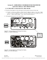
The transmitter frequency was factory-set according to strapping charts on the equipment drawings. If
necessary, the center frequency can be set via
SW3 through SW 7** (middle row).
The frequency shift
up switches can be set via
SW8-SW9*
while the frequency shift down switches can be set via
SW1-SW2*.
Table 22-2 (partial) Controls and Indicators, RFL 9780/85 Transmitter Module
Component
Designator
Name/
Description
Function
SW8-SW9*
Switch bank for shift up freq.
Sets the desired shift up frequency
SW3-SW7**
Switch bank for center frequency
Sets the desired center frequency
SW1-SW2*
Switch bank for shift down freq.
Sets the desired shift down frequency
RFL 9785
RFL Electronics Inc
.
March 1, 2013
22-
4
(973) 334-3100


