


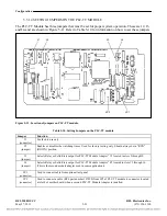


Configuration
5.3.1.2
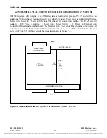
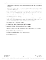
SETTING JUMPERS ON CM4 MODULE ADAPTERS
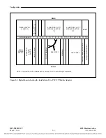
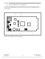
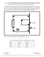
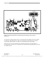
The CM4 requires a module adapter when installed in slot 1 of the Digital Chassis. This can be an MA-
271, MA-278, or an optical interface adapter. The MA-271 and MA-278 have three sets of jumpers
that must be set for proper system operation. These settings are described below in Figure 5-9. The
CM4 installed in slot 10 does not use a module adapter since it is connected to the transceiver module
through the motherboard.
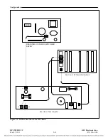
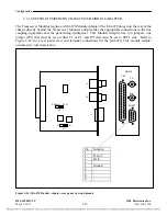
See Figures 8-7 and 8-8 for panel views and pinouts.
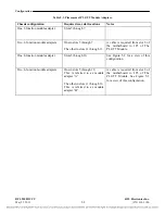
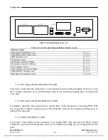
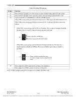
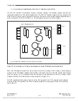
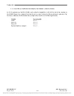
J3 Application
RFL 9508D UCC
RFL Electronics Inc.
U
Place jumper in U position to
unground the outer conductor of
the Receive Port “RX IN”. This is
the normal position for this
jumper.
G
Place jumper in G position if
outer conductor of customers
equipment “TX OUT” is not
grounded.
J2 Mode 0
J1 Mode 1
CM4 Mode
0 0 TERM
1 0 D/I-A
0 1 D/I-B
1 1 SPARE
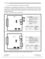
J5 Application
E1
Place jumper in E1 position for
normal E1 system operation.
Does not provide a current loop.
CSU
Place jumper in CSU position to
provide a “loop current” path
through the transformer for CSU
in T1 systems only.
J2 Mode 0
J1 Mode 1
CM4 Mode
0 0 TERM
1 0 D/I-A
0 1 D/I-B
1 1 SPARE
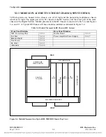
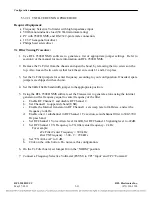
Figure 5-10. Location and use of setup jumpers on MA-271 and MA-278 Module Adapters.
MA-278
RX IN
U
J3
G
MA-271
See Figure 8-6 for front panel view
J2 J1
1 0 1 0
MODE 0 MODE 1
E1
J5
CSU
J2 J1
1 0 1 0
MODE 0 MODE 1
See Figure 8-7 for front panel view
May 27, 2011
5-19
(973) 334-3100


