


Configuration
5.3.1.3
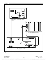
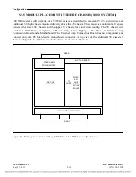
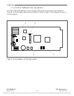
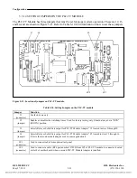
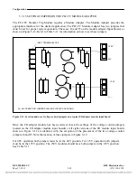
SETTING SWITCHES ON CM4 OPTICAL INTERFACE ADAPTERS
The CM4 requires a module adapter when installed in slot 1 of the Digital Chassis. This can be an MA-
271, MA-278, or an optical interface adapter. The Optical Interface adapters have two switches that
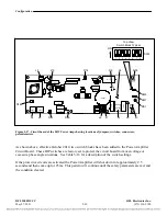
must be set for proper system operation. These are shown in Figure 5-10 and described Table 5-8
below. See Figure 8-9 for a panel view and pinouts. The CM4 installed in slot 10 does not use a
module adapter since it is connected to the transceiver module through the motherboard.
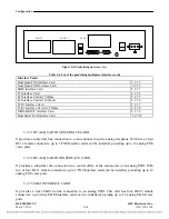
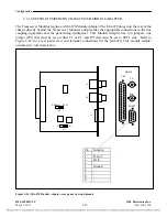
SW1
1 2
FIBER OPTIC
RECEIVER
FIBER OPTIC
TRANSMITTER
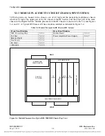
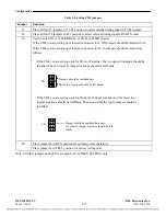
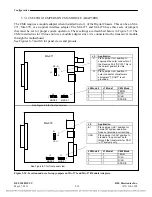
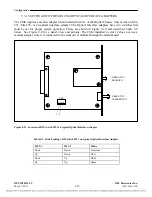
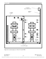
Figure 5-11. Location of DIP switch SW1 on typical Optical Interface Adapter
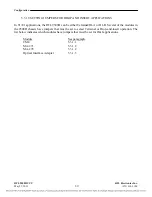
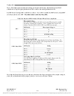
Table 5-9. Switch settings, DIP switch SW1 on typical Optical Interface Adapter
SW1-1 SW1-2
Mode
Down Down
Terminal
Up Down
DI-A
Down Up DI-B
Up Up
Spare
RFL 9508D UCC
RFL Electronics Inc.
May 27, 2011
5-20
(973) 334-3100


