RF-WM-3200B1
Shenzhen RF-star Technology Co., Ltd.
Page 23 of 35
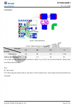
4.3 Antenna
Figure 9. Optional Antenna
Table 8. Optional Antenna Configuration
Parameter
Antenna
C27
C30
C31
L7
Chip Antenna
1 pF
NC
NC
1.8 nH
External Antenna Interface
NC
0 Ω
NC
NC
The module uses the onboard ceramic antenna by default. If you need to use an external antenna, please switch
according to the above table.
Note:
NC: Not Connect
C30: When using the external antenna, the position of C30 is measured as 0 Ω according to the actual simulation and
debugging.

