7.1.2
Overview of User Interface
Overview of DRn5020 IndraWorks Dialog
The IndraWorks software (14V20 or later) automatically shows the graphical
user interface when connected to an EFC with DRn5020 installed. The sys‐
tem can be connected and configured via USB or BUS. As the DRn5020 soft‐
ware is installed, Sytronix folder shows up in the drive tree.
Fig. 7-2:
Sytronix DRn5020 drive tree
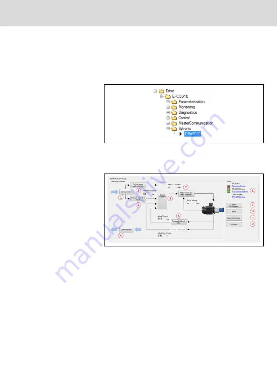
A click on DRn5020 redirects to the overview dialog of the Sytronix function.
The dialog divides into two sections. On the left side the control structure is
visible ⓛ...⑦. On the right side there are the status and system configuration
buttons which pop up the sub-dialogs ⑧...⑫.
Fig. 7-3:
Sytronix DRn5020 dialog
Any change via the dialog, the corresponding parameter will also be changed
and saved immediately. Modifying a parameter via dialog or parameter editor
are exactly the same. The DRn5020 dialog is designed for easy commission‐
ing and quick overview over the DRn system. Important ASF parameters
(F1…F4 group) can be found in this dialog and its sub-dialogs. Some impor‐
tant EFC parameters which are utilized in the DRn system can also be con‐
figured (e.g. motor control parameters). Further EFC parameters can be
found by using the EFC dialogs or by using the parameter editor.
Introduction of the DRn5020 dialog:
●
ⓛ...⑦: Communication and Control system overview
●
⑧: Status lights and Quick diagnostics
●
⑨...⑫: Commissioning and Configuration
Communication and Control System Overview
On the top level of the dialog only read-only parameters can be shown.
These parameters are greyed (can not be edited) and are showing effective
set point values and actual state values of the system. A right click on the pa‐
DOK-SYTROX-DRN5020****-IT05-EN-P
Bosch Rexroth AG
59/143
Frequency-Controlled Pump Drive System Sytronix DRn 5020
Commissioning of Sytronix DRn 5020 System


